Download
1 / 42
500 likes | 1.12k Vues
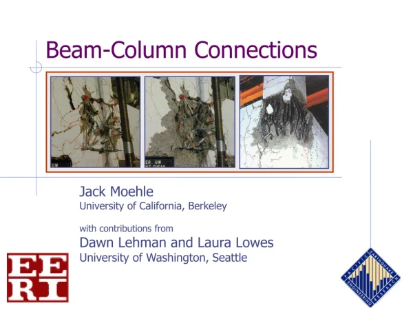
Beam-Column Connections. Jack Moehle University of California, Berkeley with contributions from Dawn Lehman and Laura Lowes University of Washington, Seattle. Outline. design of new joints existing joint details failure of existing joints in earthquakes general response characteristics

E N D
Beam-Column Connections Jack Moehle University of California, Berkeley with contributions from Dawn Lehman and Laura Lowes University of Washington, Seattle
Outline • design of new joints • existing joint details • failure of existing joints in earthquakes • general response characteristics • importance of including joint deformations • stiffness • strength • deformation capacity • axial failure
Vcol Special Moment-Resisting Frames - Design intent - For seismic design, beam yielding defines demands w Mpr Mpr Mpr Beam lc Vp Vp lnb Vp Mpr Vcol Beam Section
Vcol Ts1 = 1.25Asfy C2 = Ts2 Vb2 Vb1 C1 = Ts2 Ts2 = 1.25Asfy Vcol (b) internal stress resultants acting on joint Vcol Ts1 C2 Vu =Vj = Ts1 + C1 - Vcol (c) joint shear Joint demands (a) moments, shears, axial loads acting on joint
Interior A.1 b) Exterior A.2 c) Corner A.3 d) Roof Interior B.1 e) Roof Exterior B.2 f) Roof Corner B.3 Joint geometry(ACI Committee 352) ACI 352
Values ofg (ACI 352) Classification interior exterior corner /type cont. column 20 15 12 Roof 15 12 8 Joint shear strength- code-conforming joints - f = 0.85 ACI 352
hcol 20db Joint Details - Interior ACI 352
Joint Details - Corner ldh ACI 352
Survey of existing buildings Mosier
Studies of older-type joints Lehman
Effect of load historyinterior connections Impulsive loading history Envelope for standard cyclic history Column Shear (k) Column Bar -6 -4 -2 0 2 4 6 Story Drift Lehman
Damage at 5% drift Impulsive Loading Standard Loading Lehman
Contributions to driftinterior connections “Joints shall be modeled as either stiff or rigid components.” (FEMA 356) Specimen CD15-14 Lehman
Evaluation of FEMA-356 Modelinterior connections 18 16 14 12 10 Joint Shear Factor FEMA 8 PEER-14 CD15-14 6 CD30-14 4 PADH-14 PEER-22 2 CD30-22 PADH-22 0 0 0.005 0.01 0.015 0.02 0.025 0.03 Joint Shear Strain Lehman
Joint Deformation Joint panel deformations
Gc /5 Gc /8 Joint shear stiffnessinterior connections Gc 12 10 8 Joint shear stress (MPa) 6 4 2 0 0.000 0.005 0.010 0.015 0.020 0.025 0.030 Joint shear strain Lehman
Yield Yield Joint strengtheffect of beam yielding 1600 1200 Joint Stress (psi) 800 400 0 0 1 2 3 4 5 6 Drift (%) • Joint strength closely linked to beam flexural strength • Plastic deformation capacity higher for lower joint shear Lehman
Joint failure without yielding near 25.5√f’c Failure forced into beams between 8.5√f’cand 11√f’c Joint Shear Failure Beam Hinging/ Beam Bar Slip Joint strength interior connections - lower/upper bounds 0.4 0.3 0.2 vj /fc’ 0.1 0 0 10 20 30 40 50 60 L Lehman
Joint strengthinterior connections 3500 3000 Joint Failures 2500 2000 Joint Stress (psi) 1500 1000 500 Beam Failures 0 0 4000 8000 12000 16000 Concrete Strength (psi) Lehman
Joint deformability 1600 plastic drift capacity 1200 vmax Joint Stress (psi) 800 0.2vmax envelope 400 0 0 1 2 3 4 5 6 Drift (%)
Plastic drift capacityinterior connections 30 25 20 15 10 5 0 0 0.01 0.02 0.03 0.04 0.05 0.06 plastic drift angle Note: the plastic drift angle includes inelastic deformations of the beams
Damage progressionexterior connections Pantelides, 2002
5 Pantelides 6 Pantelides 6 Hakuto Priestley longitudinal Priestley transverse 2 Clyde 6 Clyde 4 Clyde 5 Clyde Joint behaviorexterior connections 15 10 5 0 bidirectional loading 0 1 2 3 4 5 6 7 Drift, %
Interior Exterior Plastic drift capacity 30 25 20 15 10 5 0 0 0.01 0.02 0.03 0.04 0.05 0.06 plastic drift angle Note: the plastic drift angle includes inelastic deformations of the beams
Exterior jointhook detail hook bent into joint hook bent out of joint
40 Column shear, kips 30 20 10 0 0 1 2 3 4 5 Drift ratio, % Interior joints with discontinuous bars Beres, 1992
joint geometry g • No new data. Probably still valid. 4 • Assuming bars are anchored in joint, strength limited by strength of framing members, with upper-bound of 15. For 15 ≥ ≥ 4, joint failure may occur after inelastic response. For ≤ 4, joint unlikely to fail. 6 8 • Assuming bars are anchored in joint, strength limited by strength of framing members, with upper bound of 25. For 25 ≥ ≥ 8, joint failure may occur after inelastic response. For ≤ 8, joint unlikely to fail. 10 12 Unreinforced Joint Strength FEMA 356 specifies the following:
sy tcr tcr , psi Joint failure?
Drift at “tensile failure” Drift at “lateral failure” Drift at “axial failure” Joint failure? Lateral Deflection, mm Lateral Load Priestley, 1994
Tests with axial load failure Joint test summaryaxial failures identified 0.1 } 0.08 0.10 - 0.18 0.03 - 0.07 0.20 - 0.22 Range of g values 0.36 0.06 Drift ratio Interior 0.04 Exterior, hooks bent in Exterior, hooks bent out 0.02 Corner 0 0 0.05 0.1 0.15 0.2 0.25 0.3 Axial load ratio
stiffness based on effective stiffness to yield strength = beam strength but not to exceed 8 0.02 Suggested envelope relationinterior connections with continuous beam bars 0.015 25 20 15 10 5 0 0.04 Note: the plastic drift angle includes inelastic deformations of the beams
stiffness based on effective stiffness to yield 0.010 strength = beam strength but not to exceed connections with demand less than have beam-yield mechanisms and do not follow this model 0.01 axial-load stability unknown, especially under high axial loads Suggested envelope relationexterior connections with hooked beam bars 25 20 15 10 5 0 0.02 Note: the plastic drift angle includes inelastic deformations of the beams
Joint Deformation Joint panel deformations
Methods of Repair (MOR) Pagni
Interior joint fragility relations Cosmetic repair Epoxy injection Patching Replace concrete Replace joint
Beam-Column Connections Jack Moehle University of California, Berkeley with contributions from Dawn Lehman and Laura Lowes University of Washington, Seattle
References • Clyde, C., C. Pantelides, and L. Reaveley (2000), “Performance-based evaluation of exterior reinforced concrete building joints for seismic excitation,” Report No. PEER-2000/05, Pacific Earthquake Engineering Research Center, University of California, Berkeley, 61 pp. • Pantelides, C., J. Hansen, J. Nadauld, L Reaveley (2002, “Assessment of reinforced concrete building exterior joints with substandard details,” Report No. PEER-2002/18, Pacific Earthquake Engineering Research Center, University of California, Berkeley, 103 pp. • Park, R. (2002), "A Summary of Results of Simulated Seismic Load Tests on Reinforced Concrete Beam-Column Joints, Beams and Columns with Substandard Reinforcing Details, Journal of Earthquake Engineering, Vol. 6, No. 2, pp. 147-174. • Priestley, M., and G. Hart (1994), “Seismic Behavior of “As-Built” and “As-Designed” Corner Joints,” SEQAD Report to Hart Consultant Group, Report #94-09, 93 pp. plus appendices. • Walker, S., C. Yeargin, D. Lehman, and J. Stanton (2002), “Influence of Joint Shear Stress Demand and Displacement History on the Seismic Performance of Beam-Column Joints,” Proceedings, The Third US-Japan Workshop on Performance-Based Earthquake Engineering Methodology for Reinforced Concrete Building Structures, Seattle, USA, 16-18 August 2001, Report No. PEER-2002/02, Pacific Earthquake Engineering Research Center, University of California, Berkeley, pp. 349-362. • Hakuto, S., R. Park, and H. Tanaka, “Seismic Load Tests on Interior and Exterior Beam-Column Joints with Substandard Reinforcing Details,” ACI Structural Journal, Vol. 97, No. 1, January 2000, pp. 11-25. • Beres, A., R.White, and P. Gergely, “Seismic Behavior of Reinforced Concrete Frame Structures with Nonductile Details: Part I – Summary of Experimental Findings of Full Scale Beam-Column Joint Tests,” Report NCEER-92-0024, NCEER, State University of New York at Buffalo, 1992. • Pessiki, S., C. Conley, P. Gergely, and R. White, “Seismic Behavior of Lightly-Reinforced Concrete Column and Beam Column Joint Details,” Report NCEER-90-0014, NCEER, State University of New York at Buffalo, 1990. • ACI-ASCE Committee 352, Recommendations for Design of Beam-Column Connections in Monolithic Reinforced Concrete Structures,” American Concrete Institute, Farmington Hills, 2002.
References (continued) • D. Lehman, University of Washington, personal communication, based on the following resources: • Fragility functions: • Pagni, C.A. and L.N. Lowes (2006). “Empirical Models for Predicting Earthquake Damage and Repair Requirements for Older Reinforced Concrete Beam-Column Joints.” Earthquake Spectra. In press. • Joint element: • Lowes, L.N. and A. Altoontash. “Modeling the Response of Reinforced Concrete Beam-Column Joints.” Journal of Structural Engineering, ASCE. 129(12) (2003):1686-1697. • Mitra, N. and L.N. Lowes. “Evaluation, Calibration and Verification of a Reinforced Concrete Beam-Column Joint Model.” Journal of Structural Engineering, ASCE. Submitted July 2005. • Anderson, M.R. (2003). “Analytical Modeling of Existing Reinforced Concrete Beam-Column Joints” MSCE thesis, University of Washington, Seattle, 308 p. • Analyses using joint model: • Theiss, A.G. “Modeling the Response of Older Reinforced Concrete Building Joints.” M.S. Thesis. Seattle: University of Washington (2005): 209 p. • Experimental Research • Walker, S.*, Yeargin, C.*, Lehman, D.E., and Stanton, J. Seismic Performance of Non-Ductile Reinforced Concrete Beam-Column Joints, Structural Journal, American Concrete Institute, accepted for publication. • Walker, S.G. (2001). “Seismic Performance of Existing Reinforced Concrete Beam-Column Joints”. MSCE Thesis, University of Washington, Seattle. 308 p. • Alire, D.A. (2002). "Seismic Evaluation of Existing Unconfined Reinforced Concrete Beam-Column Joints", MSCE thesis, University of Washington, Seattle, 250 p. • Infrastructure Review • Mosier, G. (2000). “Seismic Assessment of Reinforced Concrete Beam-Column Joints”. MSCE thesis, University of Washington, Seattle. 218 p.