Download
1 / 39
390 likes | 503 Vues
MATERIALS SCIENCE & ENGINEERING. Part of. A Learner’s Guide. AN INTRODUCTORY E-BOOK. Anandh Subramaniam & Kantesh Balani Materials Science and Engineering (MSE) Indian Institute of Technology, Kanpur- 208016 Email: anandh@iitk.ac.in, URL: home.iitk.ac.in/~anandh.

E N D
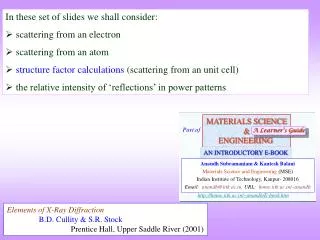
MATERIALS SCIENCE & ENGINEERING Part of A Learner’s Guide AN INTRODUCTORY E-BOOK Anandh Subramaniam & Kantesh Balani Materials Science and Engineering (MSE) Indian Institute of Technology, Kanpur- 208016 Email:anandh@iitk.ac.in, URL:home.iitk.ac.in/~anandh http://home.iitk.ac.in/~anandh/E-book.htm • In these set of slides we shall consider: • scattering from an electron • scattering from an atom • structure factor calculations (scattering from an unit cell) • the relative intensity of ‘reflections’ in power patterns Elements of X-Ray Diffraction B.D. Cullity & S.R. Stock Prentice Hall, Upper Saddle River (2001)
Intensity of the Scattered electrons Scattering by a crystal A Electron Polarization factor B Atom Atomic scattering factor (f) C Unit cell (uc) Structure factor (F) Click here to jump to structure factor calculations
A Scattering by an Electron Emission in ‘all’ directions Sets electron into oscillation Coherent(definite phase relationship) Scattered beams • The electric field (E) is the main cause for the acceleration of the electron • The moving particle radiates most strongly in a direction perpendicular to its motion • The radiation will be polarized along the direction of its motion
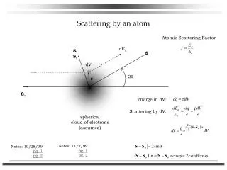
For an polarized wave z P r For a wave oscillating in z direction x Intensity of the scattered beam due to an electron (I) at a point P such that r >> The reason we are able to neglect scattering from the protons in the nucleus The scattered rays are also plane polarized
E is the measure of the amplitude of the wave E2 = Intensity For an unpolarized wave IPy = Intensity at point P due to Ey Total Intensity at point P due to Ey & Ez IPz = Intensity at point P due to Ez
Sum of the squares of the direction cosines =1 Hence In terms of 2
Scattered beam is not unpolarized Very small number • Forward and backward scattered intensity higher than at 90 • Scattered intensity minute fraction of the incident intensity
Polarization factorComes into being as we used unpolarized beam
30 20 Schematic f→ 10 0.2 0.6 0.4 0.8 1.0 (Å−1)→ B Scattering by an Atom Atomic Scattering Factor or Form Factor Scattering by an atom [Atomic number, (path difference suffered by scattering from each e−, )] • Angle of scattering leads to path differences • In the forward direction all scattered waves are in phase Scattering by an atom [Z, (, )]
30 20 Schematic f→ 10 0.2 0.6 0.4 0.8 1.0 (Å−1)→ Equals number of electrons, say for f = 29, it should Cu or Zn+ As θ↓, path difference ↓ constructive interference As λ↓, path difference ↑ destructive interference
B Scattering by an Atom BRUSH-UP • The conventional UC has lattice points as the vertices • There may or may not be atoms located at the lattice points • The shape of the UC is a parallelepiped (Greek parallēlepipedon)in 3D • There may be additional atoms in the UC due to two reasons: The chosen UC is non-primitive The additional atoms may be part of the motif
C Scattering by the Unit cell (uc) • Coherent Scattering • Unit Cell (UC) is representative of the crystal structure • Scattered waves from various atoms in the UC interfere to create the diffraction pattern The wave scattered from the middle plane is out of phase with the ones scattered from top and bottom planes. I.e. if the green rays are in phase (path difference of ) then the red ray will be exactly out of phase with the green rays (path difference of /2).
Ray 1 = R1 Ray 3 = R3 B A Unit Cell x S R Ray 2 = R2 B d(h00) a M N (h00) plane C
Independent of the shape of UC Extending to 3D Note: R1 is from corner atoms and R3 is from atoms in additional positions in UC
In complex notation • If atom B is different from atom A the amplitudes must be weighed by the respectiveatomic scattering factors (f) • The resultant amplitude of all the waves scattered by all the atoms in the UC gives the scattering factor for the unit cell • The unit cell scattering factor is called the Structure Factor (F) Scattering by an unit cell = f(position of the atoms, atomic scattering factors) For n atoms in the UC Structure factor is independent of the shape and size of the unit cell! F → Fhkl If the UC distorts so do the planes in it!! Note: n is an integer
Structure factor calculations Simple Cubic A Atom at (0,0,0) and equivalent positions All reflections are present F is independent of the scattering plane (h k l)
B C- centred Orthorhombic Atom at (0,0,0) & (½, ½, 0) and equivalent positions Real (h + k) even Both even or both odd e.g. (001), (110), (112); (021), (022), (023) Mixture of odd and even (h + k) odd e.g. (100), (101), (102); (031), (032), (033) F is independent of the ‘l’ index
If the blue planes are scattering in phase then on C- centering the red planes will scatter out of phase (with the blue planes- as they bisect them) and hence the (210) reflection will become extinct • This analysis is consistent with the extinction rules: (h + k) odd is absent
In case of the (310) planes no new translationally equivalent planes are added on lattice centering this reflection cannot go missing. • This analysis is consistent with the extinction rules: (h + k) even is present
Body centred Orthorhombic C Atom at (0,0,0) & (½, ½, ½) and equivalent positions Real (h + k + l) even e.g. (110), (200), (211); (220), (022), (310) (h + k + l) odd e.g. (100), (001), (111); (210), (032), (133) • This implies that (h+k+l) even reflections are only present. • The situation is identical in BCC crystals as well.
D Face Centred Cubic Atom at (0,0,0) & (½, ½, 0) and equivalent positions (½, ½, 0), (½, 0, ½), (0, ½, ½) Real (h, k, l) unmixed h,k,l → all even or all odd e.g. (111), (200), (220), (333), (420) (h, k, l) mixed e.g. (100), (211); (210), (032), (033) Two odd and one even (e.g. 112); two even and one odd (e.g. 122)
Mixed indices Two odd and one even (e.g. 112); two even and one odd (e.g. 122) (h, k, l) mixed e.g. (100), (211); (210), (032), (033) All odd (e.g. 111); all even (e.g. 222) Unmixed indices • This implies that in FCConly h,k,l ‘unmixed’ reflections are present. (h, k, l) unmixed e.g. (111), (200), (220), (333), (420)
E Na+ at (0,0,0) + Face Centering Translations (½, ½, 0), (½, 0, ½), (0, ½, ½)Cl− at (½, 0, 0) + FCT (0, ½, 0), (0, 0, ½), (½, ½, ½) NaCl: Face Centred Cubic
Zero for mixed indices Mixed indices (h, k, l) mixed e.g. (100), (211); (210), (032), (033)
Unmixed indices (h, k, l) unmixed h,k,l → all even or all odd e.g. (111), (222); (133), (244) If (h + k + l) is even e.g. (222),(244) If (h + k + l) is odd e.g. (111), (133)
SC F NiAl: Simple Cubic (B2- ordered structure) Al at (0, 0, 0) Ni at (½, ½, ½) Click here to know more about ordered structures Real (h + k + l) even e.g. (110), (200), (211); (220), (310) (h + k + l) odd e.g. (100), (111); (210), (032), (133) • When the central atom is identical to the corner ones we have the BCC case. • This implies that (h+k+l) even reflections are only present in BCC. This term is zero for BCC
Reciprocal lattice/crystal of NiAl Click here to know more about e.g. (110), (200), (211); (220), (310) e.g. (100), (111), (210), (032), (133)
Click here to know more about ordered structures G Al Atom at (0,0,0) Ni atom at (½, ½, 0) and equivalent positions Simple Cubic (L12 ordered structure) (½, ½, 0), (½, 0, ½), (0, ½, ½) Real Ni Al (h, k, l) unmixed h,k,l → all even or all odd e.g. (111), (200), (220), (333), (420) (h, k, l) mixed e.g. (100), (211); (210), (032), (033) Two odd and one even (e.g. 112); two even and one odd (e.g. 122)
Reciprocal lattice/crystal of Ni3Al Click here to know more about e.g. (111), (200), (220), (333), (420) e.g. (100), (211); (210), (032), (033)
Presence of additional atoms/ions/molecules in the UC can alter the intensities of some of the reflections
Relative intensity of peaks in powder patterns • We have already noted that absolute value of intensity of a peak (which is the area under a given peak) has no significance w.r.t structure identification. • The relative value of intensities of the peak gives information about the motif. • One factor which determines the intensity of a hkl reflection is the structure factor. • In powder patterns many other factors come into the picture as in the next slide. • The multiplicity factor relates to the fact that we have 8 {111} planes giving rise to single peak, while there are only 6 {100} planes (and so forth). Hence, by this very fact the intensity of the {111} planes should be more than that of the {100} planes. • A brief consideration of some these factors follows. The reader may consult Cullity’s book for more details.
Relative Intensity of diffraction lines in a powder pattern Structure Factor (F) Scattering from UC (has Atomic Scattering Factor included) Multiplicity factor (p) Number of equivalent scattering planes Polarization factor Effect of wave polarization Lorentz factor Combination of 3 geometric factors Absorption factor Specimen absorption Temperature factor Thermal diffuse scattering
Multiplicity factor * Altered in crystals with lower symmetry
Multiplicity factor * Altered in crystals with lower symmetry (of the same crystal class)
Lorentz factor Polarization factor XRD pattern from Polonium Click here for details Example of effect of Polarization factor on power pattern
Intensity of powder pattern lines (ignoring Temperature & Absorption factors) • Valid for Debye-Scherrer geometry • I → Relative Integrated“Intensity” • F → Structure factor • p → Multiplicity factor • POINTS • As one is interested in relative (integrated) intensities of the lines constant factors are omitted Volume of specimen me , e (1/dectector radius) • Random orientation of crystals in a material with Texture relative intensities are modified • Iis really diffracted energy (as Intensity is Energy/area/time) • Ignoring Temperature & Absorption factors valid for lines close-by in pattern