Download
1 / 43
470 likes | 770 Vues
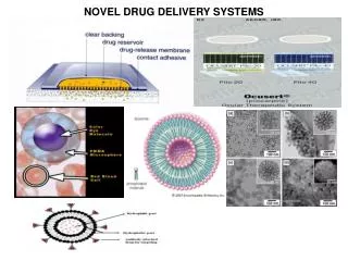
Explore BioMEMS drug delivery systems, advantages, and disadvantages, comparing passive and active devices. Learn about research areas, types of devices, and advancements in technology. Discover the innovative use of MicroCHIPS Inc. devices and thin film batteries in drug delivery applications.

E N D
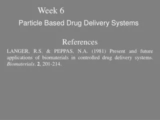
BioMEMS Implantable Drug Delivery Systems Professor Horacio Espinosa – ME381 – Final project Aaron Alexander Luke Rogers Dan Sheehan Brent Willson
Current Technology • Include hypodermic needles, pills, and passive transdermal methods • Disadvantages: • Highly Invasive • Poor Control • Can be Ineffective
Advantages Improved Control More Effective Less Intrusive Disadvantages Biocompatibility Concerns Biofouling Issues Drug Delivery by MEMS
Areas of Research • In Vivo Devices • Within the body • Implanted or Ingested • Transdermal Devices • Acts through the skin
Passive Pourous material allows diffusion Deteriorating membranes Active Electrically activated Reservoir Devices • Biocompatibilty Issues: • Toxicity and damage to tissue • Functionality (Biofouling)
Passive Simpler to manufacture No power source needed Less control Active More complex fabrication Battery required More biocompatibility concerns Much more control Several means to stimulate actuation Passive vs. Active
The “Smart Pill” • Built-in sensor to detect when the drug is required • Artificial muscle membrane to release the drug
Transdermal Devices • Currently available: • Passive • Can be ineffective and difficult to control • Improvements: • Iontophoresis • Chemical Enhancers • Ultrasound
Microneedles • Microneedles are used to improve transdermal drug delivery
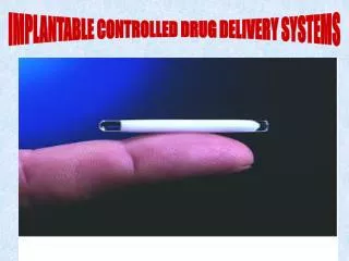
Best Device MicroCHIPS Inc. Implantable Device http://www.bu.edu/mfg/programs/outreach/etseminars/2002may/documents/santini.pdf
Best Device MicroCHIPS Inc. Implantable Device http://www.ruf.rice.edu/~rau/phys600/1959.pdf
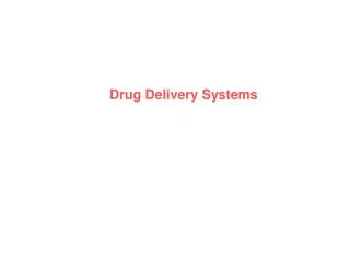
Why? • Many different configurations make it quite Versatile http://www.itnes.com/pages/batteries.html
Why? • Many different configurations make it quite Versatile • Easy to implement http://www.itnes.com/pages/batteries.html
Why? • Many different configurations make it quite Versatile • Easy to implement • Simple yet effective http://www.itnes.com/pages/batteries.html
Why? • Many different configurations make it quite Versatile • Easy to implement • Simple yet effective • Smaller in size than the “Smart Pill” http://www.itnes.com/pages/batteries.html
Start with Silicon wafer approx. 300 microns thick • PECVD 3000 angstrom thick Silicon Nitride • Silicon Nitride Patterned with Photolithography and RIE etched • KOH anisotropic etch (Silicon Nitride acts as a mask and stop) http://www.bu.edu/mfg/programs/outreach/etseminars/2002may/documents/santini.pdf
Deposit Gold Cathode and Anode • Membrane • PECVD Silicon Dioxide used as a • Dielectric • Patterned using PR and etched • with RIE • Etched to gold membrane using RIE http://www.bu.edu/mfg/programs/outreach/etseminars/2002may/documents/santini.pdf
Invert and inject drug into reservoir using inkjet technology • Reservoirs capped with Silicon Nitride http://www.bu.edu/mfg/programs/outreach/etseminars/2002may/documents/santini.pdf
Steps following fabrication • Integrated Circuitry manufactured • Combined with delivery chip and thin film battery into a compact package
Thin Film Battery • No toxic materials used http://www.ssd.ornl.gov/Programs/BatteryWeb/index.htm
Thin Film Battery • No toxic materials used • Nothing to leak into the body http://www.ssd.ornl.gov/Programs/BatteryWeb/index.htm
Thin Film Battery • No toxic materials used • Nothing to leak into the body • Can be recharged many times http://www.ssd.ornl.gov/Programs/BatteryWeb/index.htm
Thin Film Battery • No toxic materials used • Nothing to leak into the body • Can be recharged many times • 1.5 to 4.5 volts http://www.ssd.ornl.gov/Programs/BatteryWeb/index.htm
Thin Film Battery • No toxic materials used • Nothing to leak into the body • Can be recharged many times • 1.5 to 4.5 volts • Size: • .5 to 25 cm2 • 15 microns thick http://www.ssd.ornl.gov/Programs/BatteryWeb/index.htm
Battery Cross Section http://www.ssd.ornl.gov/Programs/BatteryWeb/index.htm
Actuation http://www.njnano.org/pasi/event/talks/cima.pdf
Oxidation Reduction Reaction • Au + 4Cl- [AuCl4]- + 3e- • Au + mH2O [Au(H2O)m]3+ + 3e- • 2Au + 3H2O Au2O3 + 6H+ + 6e- • 2Cl- Cl2 +2e- • Au2O3 + 8Cl- + 6H+ 2[AuCl4]- +3H2O http://ocw.mit.edu/NR/rdonlyres/Biological-Engineering-Division/BE-462JMolecular-Principles-of-BiomaterialsSpring2003/3B2F94CD-4C8D-456C-93F4-CF10C63BB014/0/BE462lect06.pdf
Activation of Redox Reaction • The in vivo environment can be considered as an aqueous NaCl solution with a PH between 6 and 7 • When a minimum of .8V is applied [AuCl4]- is the favorable state for gold in this solution. http://ocw.mit.edu/NR/rdonlyres/Biological-Engineering-Division/BE-462JMolecular-Principles-of-BiomaterialsSpring2003/3B2F94CD-4C8D-456C-93F4-CF10C63BB014/0/BE462lect06.pdf
Advantage of Implantable Drug Delivery • Conventional drug delivery such as injection or pills • Much farther from the ideal concentration over the time cycle • MEMS implantable drug delivery systems • Maintains a dosage level very close to the target rate http://www.njnano.org/pasi/event/talks/cima.pdf
Oxidation (corrosion) of Gold Reservoir Caps • A stimulus voltage is applied for 10-50 µs to start the oxidation reaction • Gold corrodes and goes into the body as harmless [AuCl4]- http://www.njnano.org/pasi/event/talks/cima.pdf
Gold Reservoir Cap http://www.njnano.org/pasi/event/talks/cima.pdf
Developing Technology Nano-channel Device Porous Hollow Silica Nanoparticles (PHSNP) Quantum Dots
Nano-channel Device • Nano-channel filter • Simpler than previous devices • Standard/Mass production • Dimensions optimized for strength
Top of Base Substrate • Drug enters entry flow chamber from entry port of top substrate • Enters input fingers, passes through nano-channels • Exits through output fingers and exit flow chamber
Glucose Release • Solution to constant drug delivery need • Drawback: drugs pass through nano-channels at different rates – electrical integration and control of flow through nano-channels
Porous Hollow Silica Nanoparticles (PHSNP) • Used in many different applications • Past drug carriers primarily oil-in-water units, liposomes, and nanoparticles and microparticles made of synthetic polymers and or natural macromolecules • PHSNP diameter = 60-70nm, wall thickness = 10nm • Synthesis of PHSNP involves CaCO3 template Fig. 3. TEM (Transmission Electron Microscope) image of PHSNP
PHSNP to carry Cefradine • Treat bacterial infection by destroying cell walls • Used for infection in airways, kidneys, post-surgery, other Fig. 1. Molecular structure of cefradine.
Distribution of Cefradine in PHSNP • PHSNP and Cefradine mixed vigorously Fig. 2. Preparation process of drug carrier from PHSNP. (a) PHSNP; (b) suspension of cefradine and PHSNP; (c) PHSNP entrapped with cefradine. Fig. 4. Distribution of pore diameters in the wall of PHSNP (a) before entrapping cefradine; (b) after entrapping cefradine.
Release of Cefradine • Stage one: 76% release in 20 min. – surface of PHSNP • Stage two: 76%-82% release in 10 hours– pores of PHSNP • Stage three: insignificant release from PHSNP hollow center • Gradual release over time can be exploited in drug delievery applications Fig. 5. In vitro release profile of cefradine from PHSNP
Quantum Dots • Crystals containing a group of electrons – usually made of II-VI semiconductor cadmium selenide • Nanometers wide, demonstrate quantum properties of single atoms, absorb and emit specific wavelengths of light • Bind Taxol, a cancer-fighting drug, and a molecule with affinity to folic acid receptors to quantum dots, also effective when bound with antibodies • Cancer cells have high concentration of folic acid receptors and can be targeted • Once excited with IR light, the bond is broken with the drug, Taxol, which is able to attack the cancerous cell
IR Illuminated Rat • Implanted with tumor • Injected with quantum dots, bound with Taxol • High concentration around tumor • Technique not as effective in humans due to deep internal organs • May be effective for skin and breast cancer