Coherent FSK
Coherent FSK. FSK = frequency shift keying Coherent = receiver have information on where the zero phase of carrier. We can treat it as non-linear modulation since information is put into the frequency. . Binary FSK. Transmitted signals are where. Binary FSK.

Coherent FSK
E N D
Presentation Transcript
Coherent FSK • FSK = frequency shift keying • Coherent = receiver have information on where the zero phase of carrier. • We can treat it as non-linear modulation since information is put into the frequency.
Binary FSK • Transmitted signals are • where
Binary FSK • S1(t) represented symbol “1”. • S2(t) represented symbol “0”. • This FSK is also known as Sunde’s FSK. • It is continuous phase frequency-shift keying (CPFSK).
Binary FSK • There are two basis functions written as • As a result, the signal vectors are
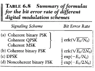
BFSK • From the figure, we have • In case of equal probability of the ones and zeros , the average probability of error is given by • We observe that at a given value of , the BFSK system requires twice as much power as the BPSK system.
Power Spectral density of BFSK • Consider the Sunde’s FSK where f1 and f2 are different by 1/Tb. We can write • We observe that in-phase component does not depend on since
Half of the symbol power Power Spectral density of BFSK • We have • For the quadrature component
Power Spectral density of BFSK • Finally, we obtain
Phase Tree of BFSK • FSK signal is given by • At t = 0, we have • The phase of Signal is zero.
Phase Tree of BFSK • At t = Tb, we have • We observe that phase changes by after one symbol (Tb seconds). - for symbol “1” and + for symbol “0” • We can draw the phase trellis as
Minimum-Shift keying (MSK) • MSK tries to shift the phase after one symbol to just half of Sunde’s FSK system. The transmitted signal is given by
MSK • Where • Observe that
MSK • h = Tb(f1-f2) is called “deviation ratio.” • For Sunde’s FSK, h = 1. • For MSK, h = 0.5. • h cannot be any smaller because the orthogonality between cos(2f1t) and cos(2f2t) is still held for h < 0.5. • Orthogonality guarantees that both signal will not interfere each other in detection process.
MSK • Phase trellis diagram for MSK signal 1101000
MSK • Signal s(t) of MSK can be decomposed into • where
MSK • For the interval –Tb< t 0, we have • Let’s note here that the for the interval -Tb<t 0 and 0< tTbmay not be the same. • We know that
MSK • Since (0) can be either 0 or depending on the past history. We have • “+” for (0) = 0 and “-” for (0) = • Hence, we have
MSK • Similarly we can write • for 0< tTb and Tb < t2Tb. Note the “+” and “-” may be different between these intervals. • Furthermore, we have that (Tb) can be /2 depending on the past history.
MSK • Hence, we have • we have that (Tb) can be /2 depending on the past history.
MSK • Hence, we have • “+” for (Tb) = +/2 and “-” for (Tb) = -/2 • The basis functions change to
MSK • We write MSK signal as • Where and
/2 0 Phase: /2 /2 -/2 0
MSK • We observe that MSK is in fact the QPSK having the pulse shape • Block diagrams for transmitter and receiver are given in the next two slides.
MSK • Probability of error of MSK system is equal to BPSK and QPSK • This due to the fact that MSK observes the signal for two symbol intervals whereas FSK only observes for single signal interval. • Bandwidth of MSK system is 50% larger than QPSK.
Noncoherent Orthogonal Modulation • Noncoherent implies that phase information is not available to the receiver. • As a result, zero phase of the receiver can mean any phase of the transmitter. • Any modulation techniques that transmits information through the phase cannot be used in noncoherent receivers.
sin(2ft) cos(2ft) Transmitter Noncoherent Orthogonal Modulation sin(2ft) cos(2ft) Receiver
Noncoherent Orthogonal Modulation • It is impossible to draw the signal constellation since we do not know where the axes are. • However, we can still determine the distance of the each signal constellation from the origin. • As a result, the modulation techniques that put information in the amplitude can be detected. • FSK uses the amplitude of signals in two different frequencies. Hence non-coherent receivers can be employed.
Noncoherent Orthogonal Modulation • Consider the BFSK system where two frequencies f1 and f2 are used to represented two “1” and “0”. • The transmitted signal is given by • Problem is that is unknown to the receiver. For the coherent receiver, is precisely known by receiver.
Noncoherent Orthogonal Modulation • Furthermore, we have • To get rid of the phase information (), we use the amplitude
Noncoherent Orthogonal Modulation • Where • The amplitude of the received signal
Noncoherent Orthogonal Modulation • Decision rule: Let if li> lkfor all k. For examples, decide if l1> l2 • This decision rule suggests that if the envelop (amplitude) of the received signal described in term of cos(2f1t) is greater than the envelop of the received signal described in term of cos(2f2t), we say s1(t) was sent.
Noncoherent Orthogonal Modulation • Consider the output of matched filter of cos(2fit).
Noncoherent Orthogonal Modulation • Envelope at t=T is • Which is exactly the same as in correlator receiver
Generalized binary receiver for noncoherent orthogonal modulation.
Quadrature receiver equivalent to either one of the two matched filters in part
Noncoherent Orthogonal Modulation • Probability of Errors
Noncoherent: BFSK • For BFSK, we have