Download
1 / 24
240 likes | 255 Vues
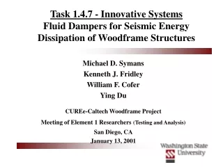
Task 1.4.7 - Innovative Systems Fluid Dampers for Seismic Energy Dissipation of Woodframe Structures. Michael D. Symans Kenneth J. Fridley William F. Cofer Ying Du CUREe-Caltech Woodframe Project Meeting of Element 1 Researchers (Testing and Analysis) San Diego, CA January 13, 2001.

E N D
Task 1.4.7 - Innovative SystemsFluid Dampers for Seismic Energy Dissipation of Woodframe Structures Michael D. Symans Kenneth J. Fridley William F. Cofer Ying Du CUREe-Caltech Woodframe ProjectMeeting of Element 1 Researchers(Testing and Analysis) San Diego, CA January 13, 2001
Outline • Review of Research Plan • Description of Shear Wall FEM • System Identification • Shear Wall Seismic Analysis • Proposed Damper Configurations • Implementation Issues • Short-Term Goals
Review of Research Plan • Phase ILiterature Review (Sept. 1999 to Dec. 1999) • Phase IIInitial Analytical Study (Dec. 1999 to May 2000) • Phase IIIIdentification of Practical Issues (Dec. 1999 to Sept. 2000) • Phase IVFinal Analytical Study (May 2000 to Dec. 2000) • Phase VRecommendations (Jan. 2001 to March 2001)
Shear Wall FEM • Wall dimensions: 2.44 m x 2.44 m (8 ft x 8 ft) • Framing: 50.8 mm x 101.6 mm (2” x 4”) nominal studs spaced at 60.96 cm (24”) • Waferboard sheathing panels: 1.22 m x 2.44 m (4 ft x 8 ft), 9.53 mm (3/8”) • Nails: 6.35 cm (2.5 in.) 8d galvanized common nails Field and perimeter nail spacing = 15.24 cm (6 in.) • Mass: 44.5 kN (10 kips) lumped at nodes along top plate at top of studs (wall located at first story of 3-story building)
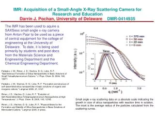
Sheathing-to-Stud Connector Element Typical Load-Deflection Curve Obtained from Static Cyclic Sheathing Connector Test (Source: Dolan, 1989) Simplified Hysteresis Loop for Sheathing Connector Element
System Identification f1 = 4.18 Hz 1 = 2.1% f2 = 22.35 Hz 2 = 7.6% f3 = 22.81 Hz 3 = 7.7%
Earthquake Loading 1952 Kern County EarthquakeTaft record - Lincoln School Tunnel (S69E component)
Pinned Connection Piston Rod Viscous Fluid Piston Head Pinned Connection Damper Configuration
Hysteretic Behavior of Wall No Damper C = 87.6 kN-s/m (500 lb-s/in)
Hysteretic Behavior of Wall(Plotted to same scale) No Damper C = 87.6 kN-s/m (500 lb-s/in)
Components of Hysteresis Loop(Plotted to same scale) C = 87.6 kN-s/m (500 lb-s/in) Wall Contribution Damper Contribution
Comparison of Components C = 87.6 kN-s/m (500 lb-s/in)
Effect of Dampers on Drift Peak drift reduced by 67% Note: 400% increase in damping capacity results in additional 26% reduction in peak drift.
Effect of Dampers on Base Shear Peak base shear reduced by 45%
Energy Distribution No Damper C = 87.6 kN-s/m - Inelastic energy dissipation demand reduced by 93 % - Portion of input energy absorbed by dampers = 82 %
Energy Distribution(Plotted to same scale) No Damper C = 87.6 kN-s/m
Pinned Connection Piston Rod Viscous Fluid Piston Head Pinned Connection Proposed Damper Configurations Dual let-in rod pin-connected to bottom cornerof wall and to damper; Damper pin-connected to upper corner
Recently Developed Amplification Systems for Stiff Structures Scissors-Jack System Toggle-Brace System
Pre-Fabricated Wall - Prefabricated in a controlled manufacturing environment (similar to Simpson Strong Wallwhich “drops” into framing) - 50.8 x 152.4 mm (2 x 6 in.) framing - Damper connections which ensure minimal slip before damper engagement.
Implementation Issues • - Taft EQ, C = 87.6 kN-s/m (500 lb-s/in): • - Damper Force Demand = 2.6 kN (580 lb) • - Damper Velocity Demand = 3.0 cm/s (1.2 in/s) • - Damper Stroke Demand = 0.2 cm (0.08 in) • - Off-the-shelf dampers (D-Series; Taylor Devices, Inc.): • - Force capacity = 2 or 8.9 kN (450 lb or 2000 lb) • - Stroke capacity = 5.1, 10.2, 15.2 or 20.3 cm (2, 4, 6, or 8 in.) • - Estimated cost = $300/damper
uw Gap element Implementation Issues Damper Engagement (effect of initial wall displacement w/out damper engagement) Fg -us/cos us uw us/cos C K Fg = gap element force us = 1/16”, 1/8”, 1/4”, 3/8”, 1/2”
Response to Comments from Element 1 Managers • Sept. 16, 2000 Meeting Comments • Analytical results need to be checked carefully (Done) • Typical detailing/connection of the dampers should be considered (In progress)
Short-Term Goals • Parametric studies of wall performance • Various earthquake records and intensities • Various damper configurations • Effect of delay in damper engagement • Development of implementation details • Analysis of 3-D Woodframe Building with dampers.