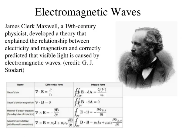
Electromagnetic waves
Electromagnetic waves. Hecht, Chapter 2 Wednesday October 23, 2002. Electromagnetic waves: Phase relations. Thus E and B are in phase since, requires that. E. k. B. Irradiance (energy per unit volume). Energy density stored in an electric field

Electromagnetic waves
E N D
Presentation Transcript
Electromagnetic waves Hecht, Chapter 2 Wednesday October 23, 2002
Electromagnetic waves: Phase relations Thus E and B are in phase since, requires that E k B
Irradiance (energy per unit volume) • Energy density stored in an electric field • Energy density stored in a magnetic field
Energy density Now if E = Eosin(ωt+φ) and ω is very large We will see only a time average of E
Intensity or Irradiance In free space, wave propagates with speed c c Δt A In time Δt, all energy in this volume passes through A. Thus, the total energy passing through A is,
Intensity or Irradiance Power passing through A is, Define: Intensity or Irradiance as the power per unit area
Intensity in a dielectric medium In a dielectric medium, Consequently, the irradiance or intensity is,
Poynting vector Define
Poynting vector For an isotropic media energy flows in the direction of propagation, so both the magnitude and direction of this flow is given by, The corresponding intensity or irradiance is then,
Example: Lasers o = 8.854 X 10⁻¹² CV-1m-1 (SI units) Laser Power = 5mW Same as sunlight at earth Near breakdown voltage in water nb. Colossal dielectric constant material CaCu3Ti4O12 , = 10,000 at 300K Subramanian et al. J. Solid State Chem. 151, 323 (2000)
Reflection and Transmission at an interface Normal Incidence – Two media characterized by v1, v2 incident transmitted reflected 1 2
Reflection and Transmission at an interface • Require continuity of amplitude at interface: f1 + g1 = f2 • Require continuity of slope at interface: f1’+ g1’= f2’ • Recall u = x – vt
Reflection and Transmission at an interface Continuity of slope requires, or,
Reflection and Transmission at an interface • Integrating from t = - to t = t • Assuming f1(t = - ) = 0 • Then,
Amplitude transmission co-efficient () Medium 1 to 2 Medium 2 to 1
Amplitude reflection co-efficient () At a dielectric interface
Phase changes on reflection from a dielectric interface n2 > n1 n2<n1 Less dense to more dense e.g. air to glass More dense to less dense e.g. glass to air phase change on reflection No phase change on reflection
Phase changes on transmission through a dielectric interface Thus there is no phase change on transmission
Amplitude Transmission & Reflection For normal incidence Amplitude reflection Amplitude transmission Suppose these are plane waves
Intensity reflection Amplitude reflection co-efficient and intensity reflection
Intensity transmission Intensity transmission and in general R + T = 1 (conservation of energy)
Two-source interference What is the nature of the superposition of radiation from two coherent sources. The classic example of this phenomenon is Young’s Double Slit Experiment Plane wave () P S1 y x a S2 L
Young’s Double slit experiment Assumptions • Monochromatic, plane wave • Incident on slits (or pin hole), S1, S2 • separated by distance a (centre to centre) • Observed on screen L >> a (L- meters, a – mm) • Two sources (S1 and S2) are coherent and in phase (since same wave front produces both as all times) • Assume slits are very narrow (width b ~ ) • so radiation from each slit alone produces uniform illumination across the screen
Young’s double slit experiment • slits at x = 0 • The fields at S1 and S2 are Assume that the slits might have different width and therefore Eo1 Eo2
Young’s double slit experiment What are the corresponding E-fields at P? Since L >> a ( small) we can put r = |r1| = |r2| We can also put |k1| = |k2| = 2/ (monochromatic source)
Young’s Double slit experiment The total amplitude at P Intensity at P
Interference Effects • Are represented by the last two terms • If the fields are perpendicular • then, • and, In the absence of interference, the total intensity is a simple sum
Interference effects • Interference requires at least parallel components of E1P and E2P • We will assume the two sources are polarized parallel to one another (i.e.
Interference terms where,
Intensity – Young’s double slit diffraction Phase difference of beams occurs because of a path difference!
Young’s Double slit diffraction • I1P = intensity of source 1 (S1) alone • I2P = intensity of source 2 (S2) alone • Thus IP can be greater or less than I1+I2 depending on the values of 2 - 1 • In Young’s experiment r1 ~|| r2 ~|| k • Hence • Thus r2 – r1 = a sin r1 r2 a r2-r1