Download
1 / 22
220 likes | 326 Vues
Learn about Stereo PIV system, translation, angular configurations, velocity components, error propagation, SPIV data reduction, camera systems, evaluation methods, calibration, and references in Fluid Mechanics. Understand distortion, mapping, and image interpolation. Explore Large-Scale PIV for river flow measurements using calibrations, marking points, distortion corrections, and velocity evaluations in open channel flow studies. Practice with EDPIV and real-world examples.

E N D
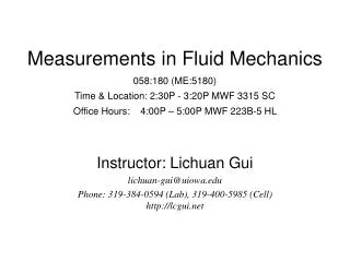
Measurements in Fluid Mechanics058:180 (ME:5180)Time & Location: 2:30P - 3:20P MWF 3315 SCOffice Hours: 4:00P – 5:00P MWF 223B-5 HL Instructor: LichuanGui lichuan-gui@uiowa.edu Phone: 319-384-0594 (Lab), 319-400-5985 (Cell) http://lcgui.net
Test region Test result Example Stereoscopic PIV • Stereo PIV system • Two cameras • Translation and angular configurations • Distorted particle images (angular system) • 3-D displacement reduced from two 2-D displacements • 3 velocity components in a plane G. Calcagno, F.D. Felice, M. Felli, and F. Pereira, 24th Sym. Naval Hydro. (2002)
X X Laser light sheet Laser light sheet Z Z X t=t0 Z S S t=t0+t X Standard PIV view Stereoscopic PIV • SPIV data reduction Z not sensible
X1 X Laser light sheet X2 Z X Z S 1 2 camera #1 camera #2 Stereoscopic PIV • SPIV data reduction Stereo view
No stereo effect in yz-plane Stereoscopic PIV • SPIV data reduction - Particle image displacements: (X’1, Y’1) and (X’2, Y’2) - Imaging scale factor: M1 and M2
Stereoscopic PIV • Error propagation in SPIV
Stereoscopic PIV • Error propagation in SPIV
Define: Stereoscopic PIV • Error propagation in SPIV
Stereoscopic PIV • Error propagation in SPIV - Optimal view angle 45
Lens Plane Camera #1 Camera #2 Stereoscopic PIV • Translation (lateral displacement) system - Object plane || Lens plane || Image plane - Uniform magnification (Mn=di/do) - Easy to focus - Off-axis angle restricted by the lens (application limited)
Object plane Lens plane Image plane Mirror pair 1 Mirror pair 2 Image #2 Test region Image #1 Aperture stop Mirror pair 1 Mirror pair 2 Stereoscopic PIV • Translation (lateral displacement) system - Single camera configuration- View angle is limited
Stereoscopic PIV • Rotational (angular displacement) system - Scheimpflug condition - Distorted image (Mnconstant)
Distorted Image Calibrated Image Velocity map Image calibration methods Preservation of straightness of lines – for high quality camera lens Polynomial mapping Stereoscopic PIV • SPIV recording evaluation 1. Evaluation with image calibration Positive: a. Uniform spatial resolution b. Simple procedure Negative: Image interpolation error
Basic evaluation steps: 1.Determine transformation function between physical and image plane Distorted Image 2.Transfer uniform evaluation grid in physical plane to image plane Velocity map Velocity calibration 3.Evaluate the distorted SPIV recordings with the transformed evaluation grid 4.Transfer the evaluated displacement components to the physical plane Stereoscopic PIV • SPIV recording evaluation 2.Evaluation with velocity calibration Positive: No image interpolation Negative: a. Non-uniform spatial resolution b. Evaluation grid transfer required
Stereoscopic PIV • References • Prasad AK (2000) Stereoscopic particle image velocimetry. Exp. Fluids 29, pp. 103-116 • Willert C (1997) Stereoscopic digital particle image velocimetry for application in wind tunnel flows. Meas. Sci. Technol. 8, pp. 1465-1479 • Practice with EDPIV • Compare image calibration and vector calibration with application example #9
Tower Camera view river City map Video set at 40m height Floating tracer Large-Scale PIV River surface flow measurement
Physical & image coordinates Calibrated image Flow filed Large-Scale PIV River surface flow measurement Original image
Physical & image coordinates - Image calibration function - inverse calibration function Large-Scale PIV Distorted image calibration - Physical coordinates (X,Y) - Image coordinates (x,y) - Calibration marking points (Xk,Yk) (xk,yk) for k=1,2,,N Minimal N=4 for determining constants bi (i=1,2,,8) Straight-line-conserved transformation
Large-Scale PIV Distorted image calibration 4 marking points >4 marking points – least square approach
Consecutive LSPIV recordings Evaluation results Example of LSPIV tests for steady water surface flow Large-Scale PIV Evaluation of LSPIV recordings - Low-Image-Density PIV mode Particle image tracking or individual particle image pattern tracking - Low Re-number in many cases Average correlation method for steady flows
Large-Scale PIV • References • Muto Y, Baba Y, Aya S (2002) Velocity measurements in open channel flow with rectangular embayments formed by spur dykes. Annuals of Disas. Prev. Res. Inst., Kyoto Univ., No.45B-2 • Fujita I, Aya S, Deguchi T (1997) Surface velocity measurement of river flow using video images of an oblique angle. Proc. 27th IAHR Cong., San Francisco, Vol.B, No.1, pp.227-232 • Practice with EDPIV • Work with sample: IMAGE GROUP: DISTORTED PIV IMAGES