Download
1 / 25
250 likes | 390 Vues
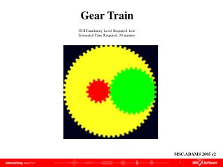
Gear Train GUI Familiarity Level Required: Low Estimated Time Required: 30 minutes. MSC.ADAMS 2005 r2. Topics Covered. In this tutorial you will learn how to:. Import gear macro Create a Cylinder Create gear geometry Create revolute joint Create gear joints Add motion Simulate.

E N D
Gear Train GUI Familiarity Level Required: Low Estimated Time Required: 30 minutes MSC.ADAMS 2005 r2
Topics Covered In this tutorial you will learn how to: • Import gear macro • Create a Cylinder • Create gear geometry • Create revolute joint • Create gear joints • Add motion • Simulate You will need to download “gear_macro.zip” to be able to complete this tutorial If you have any difficulties, import the “gear_train_shortcut1.cmd” file and proceed from pg 16 If you have any difficulties, import the “gear_train_shortcut2.cmd” file and proceed from pg 19 If you have any difficulties, import the “gear_train_complete.cmd” file and proceed from pg 23
Gear Train Problem Create a gear train. Which has a pinion gear rotating a gear, thus rotating the planet gear
What You Should Accomplish When you complete this tutorial you will have a gear train showing gears that mesh internally and externally.
Gear Macro • Download the files “gear_mac.cmd” and “setup_gear_macro.cmd “ and save them into the same directory as ADAMS/View is installed a
Importing Macro • Click Import a File radio button • Click OK a b c • Right-click File to Read text box. Choose Browse… d e • Search you directory to find the folder you saved the macro. • Click on “setup_gear_macro” • Click Open f
Change Units • Click Settings menu, then Units… • The Units Settings window will appear • Select Centimeter from the Length pull down menu • Click OK b a c
Change Settings • To edit the grid size: • Click Settings menu, then Working Grid… • The Working Grid Settings window will appear • Change the Spacing text fields in X and Y to (10mm) • Click OK a b c
Creating a Marker • Click View menu, select Coordinate Window • Select Marker from the tool stack • Create a Marker at point (0,0,0) • Create another marker at point (20,0,0) b c d a
Create Cylinder • Select Cylinder from rigid Body tool stack • Turn onRadius checkbox • Enter (5.0cm) in Radius text field • Click point (-5,0,0) • Click point (-4,0,0) a d e b c
Rotate Cylinder • Right click center of cylinder, select Marker: MARKER_3 Modify • in Orientation text field enter 90.0, 0.0, 0.0 • Click OK a b c
Create Gear Geometry • Click Build menu, Select Create Gear Geometry • Enter Marker_3 in Center Marker text field • Enter ( 4.5 cm ) in Inner Radius text field • Enter ( 5.5 cm ) in Outer Radius text field • Enter 15 in Number Of Teeth text field • Enter ( 2.0 cm ) in Thickness text field • Enter pinion in Gear Name text field • Click Ok b c d e f g h a
Add Revolute Joint • Right-click on the Joint tool stack, select Joint: Revolute tool. • Set the Construction option menu to 1 Location and Normal to Grid. • Left-click on the marker PART_2.MARKER_1 at the center of the cylinder. • A joint between the cylinder and the ground is created at that location. a c d b
Add a Motion • Right-click motion tool stack, select Rotational Motion tool • Enter (360d) in Speed text field • Click on JOINT_1 a c b
Changing Appearance • Right click on the gear, select Appearance from Cylinder:CYLINDER_1 menu • Turnoff the Off Visibility radio button • Check your model • Click on the Simulation tool • Click Play button c b d a
Create Gear Create a second gear with radius of (10cm) at point (10,0,0) Create a revolute joint in the center
Create Gear Joint • Right-click on joint tool stack, select Gear Joint • Right click text field in Joint Name, select Joint Pick choose the revolute joint on the pinion (JOINT_1) • Right click text field in Joint Name, select Joint Pick choose the revolute joint on the gear (JOINT_2) • Right click text field in Common Velocity Marker, select Marker Pick choose ground MARKER_1 • Click OK a c b d e
Revolving a Gear Joint • Right click center of gear joint, select Marker:MARKER_1 Modify • In Orientation text field enter 0.0, 90.0, 0.0 • Click OK a b c Run simulation to test gear joint
Aligning Gears • Right click center of gear joint, select Modify from –Marker:MARKER_3 menu • in Orientation text field enter 82.0, 0.0, 0.0 • Click OK a b c
Create Gear Create another gear of radius (20cm) at point (0,0,0) Enter these values:
Create Gear Joint • Create another Gear Joint between the gear and the planet a • Modify MARKER_2 • Rotate 90 deg in Y-dir b c
Verify • Right-click Information button, select Verify a The information screen will open up There should be 0 Degrees of Freedom and no redundant constraints Run a simulation to verify your model works properly
What You Should Accomplish When you complete this tutorial you will have a gear train showing gears that mesh internally and externally
Topics Covered In this tutorial you will learn how to: • Import gear macro • Create a Cylinder • Create gear geometry • Create revolute joint • Create gear joints • Add motion • Simulate
Best Practices • Make sure the units are correctly set. • Make sure the revolute joint is in the correctdirection. • Check dimensions of your parts to make sure they are correct. • Check orientation of the parts and joints to make sure it is correct. • Make sure your model verification is successful • Make sure the measures are set properly. • Make sure the plot is displaying the correct set of results.