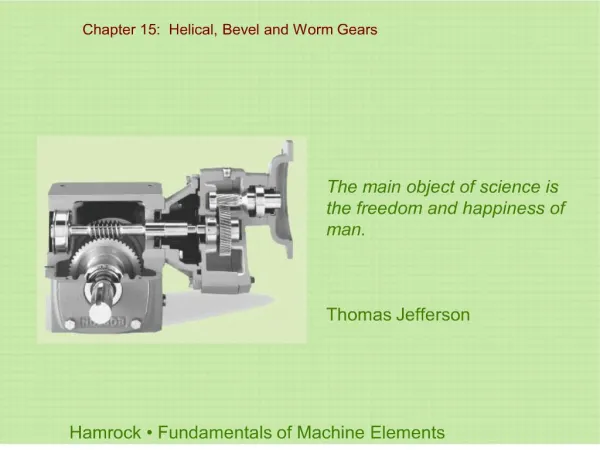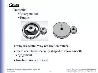
Bevel Gears
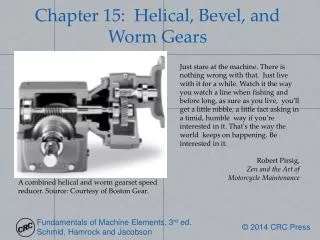
Straight Tooth Bevel Gear. Hypoid Bevel Gear. Spiral Bevel Gear. σ =bending stress. W t = the tangential force at the midpoint of the tooth. W a = the axial force. W r = the radial force. H = the Horsepower transferred to the gear from the pinion.

Bevel Gears
E N D
Presentation Transcript
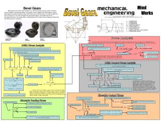
Straight Tooth Bevel Gear Hypoid Bevel Gear Spiral Bevel Gear σ =bending stress Wt = the tangential force at the midpoint of the tooth. Wa = the axial force. Wr = the radial force H = the Horsepower transferred to the gear from the pinion Wt = transmitted tangential load computed using the pitch radius at the large end of the gear teeth Ka = application factor (compensates for situations where the actual load exceeds the nominal tangential load Wt and is assigned by the engineer) γ = Pitch angle of the gear. Pd = nominal diametral pitch in plane of rotation = the diameter of the pinion Ks = size factor (typically unity, but included to account for nonuniformity in material properties) Ca = application factor (compensates for situations where the actual load exceeds the nominal tangential load Wt and is assigned by the engineer) = the diameter of the gear Km = load distribution factor σc = absolute value of contact stress J = bending strength geometry factor F = face width F = face width n = the speed that the pinion rotates for V in ft/min V = pitch-line velocity Cf = surface-condition factor (no currently established values, but values greater than unity recommended in the presence of obvious surface defects) for V in m/s A=50+56(1-B) B=(12-Qv)(2/3)/4 d = pitch diameter of pinion Cp = elastic coefficient rp = the average pitch radius, this is the distance from the center of the pinion to the midpoint of the gear tooth Qv = AGMA transmission accuracy-level number Sc = AGMA surface fatigue strength (from AGMA graphs or tables) Cv = dynamic factor (given by the same equation as Kv in bending stress formula) HBP and HBG = Brinell harnesses of pinion and gear, respectively σ = Allowable bending stress: CL = life factor (from AGMA graph) Cm = load-distribution factor CH = 1.0 + A(mG – 1.0) (only valid when (HBP / HBG) ≤ 1.7 ) St = AGMA bending strength (from AGMA graphs or tables) I = geometry factor σ = Allowable Contact stress: CH = hardness-ratio factor (used only for the gear) Cs = size factor (typically unity, but included to account for nonuniformity in material properties) KL = life factor (from AGMA graph) dG = pitch diameter of gear dP = pitch diameter of pinion KR = CR = 0.7 – 0.15 log (1 – R ) 0.9 ≤ R < 0.99 KT = temperature factor (unity up to gear-blank temperatures of 250°F , greater than unity for higher temperatures) R = reliability corresponding to 107 cycles of life KR = CR = 0.5 – 0.25 log (1 – R ) 0.99 ≤ R < 0.9999 CR = reliability factor KR = reliability factor CT = temperature factor (unity up to gear-blank temperatures of 250°F , greater than unity for higher temperatures) Mind Works Bevel Gears Bevel gears have their teeth formed on a conical surface and are used to transfer motion between intersecting shafts. This poster covers straight-tooth bevel gears. Spiral bevelgears are quite similar but have their teeth cut so that they are no longer straight but form a circular arc. For both straight and spiral bevel gears, the shafts have to be perpendicular and in the same plane. Hypoid gears can transfer motion between shafts that are offset and don’t intersect. Bevel Gears By: Brian Chamberlin, Luke Rust, and Bryan Blakey Source: Mechanical Engineering Design, 5th Edition, Shigley and Mischke, McGraw-Hill, 1989 Force Analysis Goal: Find the force (W) that would occur if all the forces were concentrated at the midpoint of the gear tooth. This force is composed of three component forces, a tangential, a radial and an axial force. Once the force acting at the midpoint we can perform a simple statistical analysis to find the reactions in the shaft and/or the bearings. AGMA Stress Analysis The tangential force is due to the amount of power transferred to the gear as well as the pitch line velocity. Once we calculate the tangential force we can find the radial and axial forces if we now the pressure angle, and the pitch angle of the gear. AGMA Contact Stress Analysis Cp is obtained from a Hertzian stress analysis of contacting spheres, and values are given in AGMA tables. Similarly, values for geometry factor I can be taken from AGMA graphs for various bevel gear geometries. The load distribution factor Cm is included to account for misalignment of rotational axes, deviations in lead, and load-caused elastic deflections of shafts, bearings, and/or housing. The values for Cm can be found in a table based on conditions of support and face width. Note: all values apply to the large end of the teeth. Typically, values for Kv are plotted vs. values of V and can be taken from AGMA dynamic factor graphs. Similarly, values for geometry factor J can be taken from AGMA graphs for various bevel gear geometries. The load distribution factor Km is included to account for misalignment of rotational axes, deviations in lead, and load-caused elastic deflections of shafts, bearings, and/or housing. The values for Km can be found in a table based on conditions of support and face width. Allowable Contact Stress Allowable Bending Stress