Proton Driver Solutions for High-Energy Neutrino Factory
260 likes | 369 Vues
Explore advanced proton driver systems for Neutrino Factory applications, focusing on power, energy, bunch length, and rep rate requirements. Study upgrade scenarios, linac enhancements, and accelerator optimizations.

Proton Driver Solutions for High-Energy Neutrino Factory
E N D
Presentation Transcript
NufactRAL and CERN p-drivers S. Gilardoni – CERN Based on contributions from:J. Thomason, ISIS Accelerator Division M. Aiba, E. Benedetto, R. Garoby and M. Meddahi, CERN
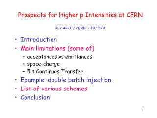
Multi-MW p-driver • Basic requirements: • 4 MW power on target • Energy between 5 – 15 GeV • RMS bunch length 1 – 3 ns • 50 Hz rep. rate. • 3 bunches, spaced by more than 80 μs
Proton Driver for a Neutrino Factory Chris Prior, Grahame Rees, Shinji Machida ( ) • Lower injection energies provide smaller • bucket area in the ring and the • small longitudinal emittance • needed for final ns bunch • compression. Studies • show that 180 MeV is a • realistic energy for NF • Separate main ring with optics chosen • for ns bunch compression. Could • be FFAG (cheaper but • insufficiently developed) or • a synchrotron (reliable, • tried and tested) • Special achromat for • collimation (longitudinal • and transverse) and • momentum ramping for • injection • Compressed • bunches need to be held and sent to • target at intervals of ~100 μs. Possible in FFAG and also synchrotron with flat top • Separate booster ring • designed for low loss phase • space painting for beam injection • and accumulation. Synchrotron moving • buckets give flexibility to capture all of the • injected beam 10 GeV RCS
ISIS Upgrades • Present operations for two target stations • Operational Intensities: 220 – 230 μA (185 kW) • Experimental Intensities of 31013 ppp (equiv. 240 μA) • DHRF operating well: High Intensity & Low Loss • Now looking at overall high intensity optimisation • Study ISIS upgrade scenarios 0) Linac and TS1 refurbishment 1) Linac upgrade leading to ~0.5 MW operations on TS1 Overlap with NF proton driver 2) ~3.3 GeV booster synchrotron: MW Target 3) 800 MeV direct injections to booster synchrotron: 2 – 5 MW Target 4) Upgrade 3) + long pulse mode option
ISIS MW Upgrade Scenarios 1) Replace ISIS linac with a new ≈ 180 MeV linac (≈ 0.5MW) 2) Based on a ≈ 3.3 GeV RCS fed by bucket-to-bucket transfer from ISIS 800 MeV synchrotron (1MW, perhaps more) 3) RCS design also accommodates multi-turn charge exchange injection to facilitate a further upgrade path where the RCS is fed directly from an 800 MeV linac (2 – 5 MW)
ISIS MW Upgrade Scenarios 1) Replace ISIS linac with a new ≈ 180 MeV linac (≈ 0.5MW) 2) Based on a ≈ 3.3 GeV RCS fed by bucket-to-bucket transfer from ISIS 800 MeV synchrotron (1MW, perhaps more) 3) RCS design also accommodates multi-turn charge exchange injection to facilitate a further upgrade path where the RCS is fed directly from an 800 MeV linac (2 – 5 MW)
ISIS MW Upgrade Scenarios 1) Replace ISIS linac with a new ≈ 180 MeV linac (≈ 0.5MW) 2) Based on a ≈ 3.3 GeV RCS fed by bucket-to-bucket transfer from ISIS 800 MeV synchrotron (1MW, perhaps more) 3) RCS design also accommodates multi-turn charge exchange injection to facilitate a further upgrade path where the RCS is fed directly from an 800 MeV linac (2 – 5 MW)
800 MeV, Hˉ Linac Design Parameters Grahame Rees, Ciprian Plostinar ( )
Common Proton Driver for theNeutron Source and the Neutrino Factory • Based on MW ISIS upgrade • with 800MeV Linac and 3.2 • (≈ 3.3) GeV RCS • Assumes a sharing of the beam • power at 3.2 GeV between the • two facilities • Both facilities can have the • same ion source, RFQ, chopper, • linac, H− injection, accumulation • and acceleration to 3.2 GeV • Requires additional • RCS machine in • order to meet • thepower • and energy • needs of the • Neutrino Factory • Options for the bunch compression to 1 – 3 ns RMS bunch length: • - adiabatic compression in the RCS • - ‘fast phase rotation’ in the RCS • - ‘fast phase rotation’ in a dedicated compressor ring
Preliminary design of the second RCS Jaroslaw Pasternak, Leo Jenner ( , , ) Parameters of 3.2 – 9.6 GeV RCS • Present-day, cost-effective RCS technology • Only three quadrupole families • Allows a flexible choice of gamma transition • Up to 3.7 MV/turn?
SPL-Based NFProton Driver Nearly GreenFieldSolution
LP-SPL: Low Power-Superconducting Proton Linac (4 GeV) Proton flux / Beam power Back-up LIU (2019) Present Main requirements of PS2 on its injector: 50 MeV Linac2 Linac4 Linac4 160 MeV HP-SPL: Upgrade of infrastructure (cooling water, electricity, cryogenics etc.) Replacement of klystron power supplies Addition of 5 high bcryomodules to accelerate up to 5 GeV 1.4 GeV PSB LP-SPL 2.0 GeV PSB 4 GeV PS PS 26 GeV PS2 50 GeV Output energy SPS 450 GeV LHC / sLHC 7 TeV
SPL-Based Proton Driver: Principle Accumulation of beam from the High Power SPL in a fixed energy Accumulator (5 GeV, 4MW beam power). Bunch compression («rotation») in a separate Compressor ring
SPL front end (Linac4): block diagram Linac4: 80 m, 18 klystrons 45keV 3MeV 3MeV 50MeV 94MeV 160MeV H- RFQ CHOPPER DTL CCDTL PIMS RF volume source (DESY) 45 kV Extrac. Radio Frequency Quadrupole 3 m 1 Klystron 550 kW Chopper & Bunchers 3.6 m 11 EMquad 3 cavities Drift Tube Linac 18.7 m 3 tanks 3 klystrons 4.7 MW 111 PMQs Cell-Coupled Drift Tube Linac 25 m 21 tanks 7 klystrons 7 MW 21 EMQuads Pi-Mode Structure 22 m 12 tanks 8 klystrons ~12 MW 12 EMQuads Ion current: 40 mA (avg.), 65 mA (peak) RF accelerating structures: 4 types (RFQ, DTL, CCDTL, PIMS) Frequency: 352.2 MHz Duty cycle: 0.1% phase 1 (Linac4), 3-4% phase 2 (SPL), (design: 10%)
Linac4 building Oct 2010 Linac4 Mar 2011 First user
HP-SPL: Main Characteristics Required for low loss in accumulator Ion species H− Output Energy 5 GeV Bunch Frequency 352.2 MHz Repetition Rate 50 Hz High speed chopper < 2 ns (rise & fall times) Required for muon production Required for flexibility and low loss in accumulator 2 ´ beam current Þ 2 ´ nb. of klystrons etc .
HP-SPL: Block Diagram 110 m 0.73 GeV 0 m 0.16 GeV 291 m 2.5 GeV 500 m 5 GeV Medium b cryomodule High b cryomodules High b cryomodules Debunchers Ejection From Linac4 To HP-PS and/or Accumulator to EURISOL 9 x 6 b=0.65 cavities 13 x 8 b=1 cavities 11 x 8 b=1 cavities • Segmented cryogenics / separate cryo-line / room temperature quadrupoles: • Medium b (0.65) – 3 cavities / cryomodule • High b (1) – 8 cavities / cryomodule Low energy Intermediate energy High energy
HP-SPL: R&D Objective Design, construction and test of a string of 4 b=1 cavities equipped with main couplers & tuners inside a “short” prototype cryo-module before the end of 2014 tested in 2014. Cryomodule (CERN – CNRS)
HP-SPL: Cavity & Cryomodule Design SPL b = 1 cavity + helium tank + tuner + main coupler Bulk niobium cavities (CERN) HOM coupler (CERN – Uni Rostock) Helium tank (CERN – CEA) Tuner (CEA) Main coupler (CERN)
Accumulator/compressor lattices from M. Aiba
HP-SPL: Cost Estimate (1/3/12) • HP-SPL cost estimate - sLHC-Project-Note-0037 (F. Gerigk, CERN-BE-RF, public) • Cost estimate : 806.9 MCHF • Very detailed • Include services, tunnels, L4 upgrade, even T-line to PS2 • Does not include contingency • Does not include Linac4 (~100 MCHF)