Bonded Concrete Overlay (BCO) Training Module for Improved Pavement Performance
860 likes | 888 Vues
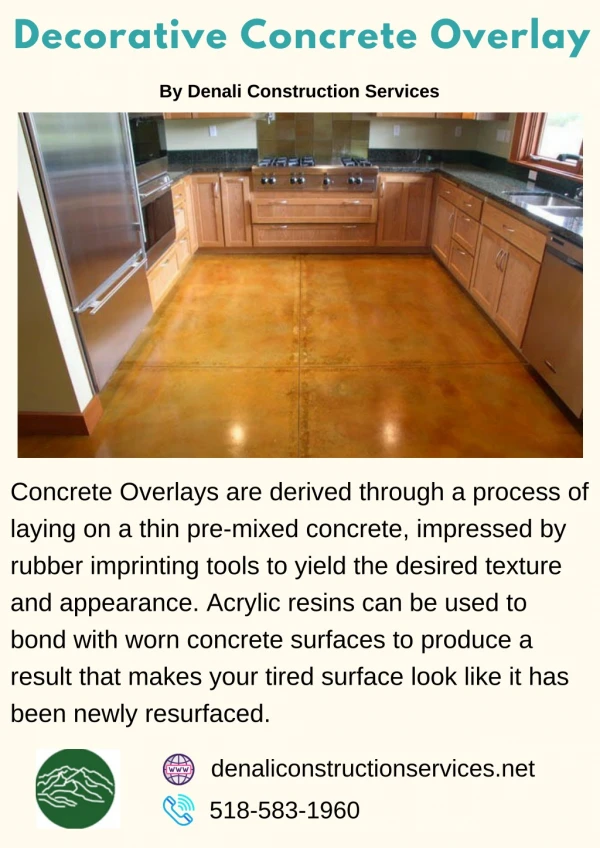
This comprehensive training module covers the design and construction of bonded concrete overlays, focusing on enhancing structural capacity of existing pavements. Learn the current AASHTO design methods with detailed procedures, evaluation techniques, and capacity determination for efficient pavement rehabilitation. Suitable for professionals in the transportation and construction industries.

Bonded Concrete Overlay (BCO) Training Module for Improved Pavement Performance
E N D
Presentation Transcript
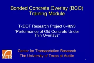
Bonded Concrete Overlay (BCO) Training Module TxDOT Research Project 0-4893 “Performance of Old Concrete Under Thin Overlays” Center for Transportation Research The University of Texas at Austin 1
Acknowledgement • PC – Charles Gaskin, P.E. (HOU) • PD – German Claros, Ph.D., P.E. (RTI) • PA – Joe Leidy, P.E. (CSTMP) – Darlene Goehl, P.E. (BRY) – Hua Chen, P.E. (CSTMP) 2
Training Module Contents • BCO Design Module • BCO Construction Module • BCO in Texas – Lessons Learned 3
Scope • Primarily, continuously reinforced concrete pavement (CRCP) overlay on CRCP • CRCP overlay on JCP is not fully covered. 4
Bonded Concrete Overlay- Overview - • Consists of concrete layer (2 to 8 inches) on top of an existing concrete surface. • One of the most cost-effective way of enhancing structural capacity of under-designed pavements • Specific steps are taken to bond the new concrete overlay to the existing concrete. • Increases structural capacity of the pavement system by reducing deflections. 5
Bonded Concrete Overlay (BCO) Design Currently, the AASHTO 1993 Guide is the most widely used design method for bonded overlay. 8
AASHTO DESIGNRevisions in the 93 Guide Overlay Design was Completely Revised • New Procedure consists of 7 Overlay Design Procedures • Uses the Concept of Structural Deficiency • Used for Structural Overlay Design 9
Capacity after Rehabilitation Capacity of Overlay Effective Capacityof ExistingPavement Structural Deficiency Approach to Overlay Design Original Capacity Structural Capacity Loads 10
Pavement Evaluation for Overlay Design Functional Evaluation of Existing Pavement • Surface Friction Problems/Polishing • Use Diamond Grinding or Grooving to Restore Skid Resistance • Surface Roughness • Use CPR and Diamond Grinding. 11
AASHTO Bonded Concrete Overlay Design Procedure 1. Collect Existing Pavement Information. 2. Predict Future ESALs 3. Perform Condition Survey 4. Perform Deflection Testing (Recommended) 5. Perform Coring / Materials Testing (Recommended) 6. Determine Future Structural Capacity (TxDOT Design Procedures for New PCC Pavement) 7. Determine Existing Structural Capacity 8. Determine Overlay Structural Capacity and Thicknesses 15
AASHTO OVERLAY DESIGN Procedure 1. Collect Existing Pavement Information • Existing Slab or Layer Thicknesses • Type of Load Transfer Mechanism • Type of Shoulder • Base/Subbase information • Soils Information 16
AASHTO OVERLAY DESIGN Procedure 2. Predict Future ESALs • Predicted Future 18KESAL's in the Design Lane over the Design Period • Past ESAL's if the Remaining Life Method is used to determine Structural Capacity of the Existing Pavement 17
AASHTO OVERLAY DESIGNLoadings ESAL SELECTION EXISTING OVERLAY PAVEMENT TYPE JPCP or JRCP PCC or AC Rigid CRCP PCC or AC Rigid AC PCC Rigid COMPOSITE PCC or AC Rigid Note: Flexible ESALs 2/3 Rigid ESALs 18
AASHTO OVERLAY DESIGN Procedure 3. Perform Condition Survey • Number of punchouts per mile • Number of deteriorated transverse cracks per mile • Number of existing and new repairs prior to overlay per mile • Presence and general severity of PCC durability problems (D-cracking or ASR) • Evidence of pumping of fines or water
AASHTO OVERLAY DESIGN Procedure 4. Perform Deflection Testing 20
AASHTO OVERLAY DESIGN Nondestructive Deflection Testing (NDT) • Estimate Effective k-value • Examine Load Transfer Efficiency at Joints and Cracks • Examine Resilient Modulus of Pavement Layers • Quantify Variability Along the Project 21
AASHTO OVERLAY DESIGN Procedure 5. Perform Coring & Materials Testing The surveys and testing are used to estimate the in-situ material properties and the condition of the pavement and underlying layers. 23
AASHTO OVERLAY DESIGN Procedure 6. Determine Future Structural Capacity • Df = Slab Thickness Required to Carry Future Traffic Loadings • Use TxDOT’s Pavement Design Procedures for New PCC Pavements 24
Determination of Required Thickness for Future Traffic Factors Required for Slab Thickness Serviceability (po, pt) Traffic (ESALs, E-18s) Load Transfer (J) Concrete Properties (S’c, Ec) Subgrade Strength (k, LS) Drainage (Cd) Reliability (R, So) 25
AASHTO OVERLAY DESIGN Procedure 7. Determine Structural Capacity of Existing Pavement • Deff = Effective Slab Thickness of the Existing Pavement 26
AASHTO OVERLAY DESIGN Structural Capacity Determination Structural Capacity of Existing Pavement is evaluated by two methods: 1. Visual Survey 2. Fatigue Damage Due to Traffic (Remaining Life Method) 28
AASHTO OVERLAY DESIGN Structural Capacity Determination A. Visual Survey • Visual Survey - Deteriorated Transverse and Longitudinal Joints and Cracks Localized failing Areas Localized Punchouts in CRCP 29
AASHTO OVERLAY DESIGN Structural Capacity Determination B. Fatigue Damage Due to Traffic (Remaining Life) • Uses Estimate of Past Traffic to Determine Existing Damage • Remaining Life Determined from Past Traffic and Expected Future Traffic 30
Effective Slab Thicknessby Visual Survey Method EFFECTIVE SLAB THICKNESS (Deff) Deff = Fjc * Fdur * Ffat * D Where Fjc = Joints and Cracks Adjustment Factor Fdur =Durability Adjustment Factor Ffat = Fatigue Adjustment Factor D = Thickness of Existing Slab, in. 31
Bonded Concrete Overlay Joints & Cracks Adjustment Factor, (Fjc) Adjusts for PSI loss due to unrepaired joints, cracks, and other discontinuities Pavements with no ”D” cracking or reactive aggregates • Number of deteriorated transverse joints per mile • Number of deteriorated transverse cracks per mile • Number of existing expansion joints, exceptionally wide joints (>1 in.), or AC full-depth patches Do not include joints or cracks with “D” cracking or reactive aggregate deterioration 32
Bonded Concrete Overlay Joints & Cracks Adjustment Factor, (Fjc) 33
Bonded Concrete Overlay THICKNESS DESIGN Dol = Df - Deff Where Dol = Required Slab Thickness of Overlay, in. Df = Slab Thickness to Carry Future Traffic, in. Deff = Thickness of Existing Slab, in. 36
BCO Design Procedures Thickness Needed for Future Traffic (13-in) Effective Thickness of Existing Pavement (10-in 8-in) Determine Overlay Thickness (13 – 8 = 5 in for BCO) 37
Bonded Concrete Overlay Joints & Cracks Adjustment Factor, (Fjc) Fjc = 1.0
Bonded Concrete Overlay Durability Adjustment Factor, (Fdur) Adjusts for PSI loss due to durability problems, such as “D” cracking and reactive aggregates • 1.00 No durability problems • 0.96-0.99 Durability cracking exists, no spalling • 0.88-0.95 Substantial cracking, some spalling • 0.80-0.87 Substantial cracking, Severe spalling Fdur = 1.0 (no durability problems)
Bonded Concrete Overlay Fatigue Adjustment Factor, (Ffat) Adjusts for PSI loss due to fatigue damage in the slab • 0.97-1.00 Few Cracks / punchoutsJPCP: <5% Slabs cracked JRCP: <25 working cracks/mile CRCP: < 4 punchouts/mile • 0.94-0.96 Significant cracking / punchoutsJPCP: 5-15% Slabs cracked JRCP: 26-75 working cracks/mile CRCP: 4-12 punchouts/mile • 0.90-0.94 Extensive cracking / punchoutsJPCP: >15% Slabs cracked JRCP: >75 working cracks/mile CRCP: >12 punchouts/mile Ffat = 0.97
DETERMINATION OF EFFECTIVE SLAB THICKNESS (Deff) Deff = Fjc * Fdur * Ffat * D Where Fjc = Joints and Cracks Adjustment Factor Fdur =Durability Adjustment Factor Ffat = Fatigue Adjustment Factor D = Effective Thickness of Existing Slab, in. Deff = 1.0 * 1.0 * 0.97 * 8 = 7.75-in
Bonded Concrete Overlay THICKNESS DESIGN Dol = Df - Deff Where Dol = Required Slab Thickness of Overlay, in. Df = Slab Thickness to Carry Future Traffic, in. Deff = Thickness of Existing Slab, in. Dol = 12.5 – 7.75 = 4.75 in: Use 5-in for BCO.
Reinforcement The amount of longitudinal reinforcement: about 0.6 % of concrete cross-sectional area. 48
BCO Construction Module • Material Selection • Pre-overlay repair • Surface Preparation • Reinforcement • Concrete Placement • Finishing • Curing 51
Material Selection • Concrete material properties in new layer are critical for the good performance of BCO. • More specifically, coarse aggregate type is of utmost importance. • Coarse aggregate with low CTE and modulus of elasticity is most desirable. 52
Material Selection • Fiber or no fiber? • For thin BCO, up to 3-in., fibers appear to improve performance. • For thicker BCO, fibers do not seem to help. 53