Download
1 / 75
840 likes | 1.64k Vues
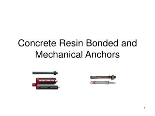
Concrete Resin Bonded and Mechanical Anchors. Purpose: Develop a design procedure for resin bonded and mechanical anchors to be used in the ODOT BDDM. Design Codes Used: Mechanical Anchors: American Concrete Institute (ACI) Appendix D of ACI 318-08

E N D
Purpose: Develop a design procedure for resin bonded and mechanical anchors to be used in the ODOT BDDM
Design Codes Used: Mechanical Anchors: American Concrete Institute (ACI) Appendix D of ACI 318-08 (PCI Design Handbook referenced for conformity) Resin Bonded Anchors: International Code Council (ICC) Section AC308
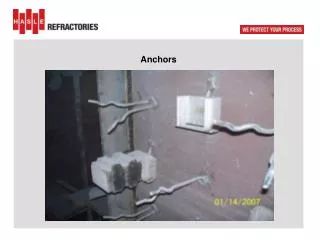
General Description: • Mechanical Anchor: A pre-installed or cast-in-place metal anchor. Pre-installed anchors have headed or hooked ends and are cast in the concrete. Post installed anchors placed in drilled holes and have an expanding mechanism near the bottom of the anchor that applies compressive stress to the surrounding concrete in order to provide tensile resistance of the anchor. • Resin Bonded Anchor: A post-installed metal anchor that is bonded to the concrete with an epoxy resin that is injected into the drilled hole after the anchor is placed.
Single Mechanical Anchor Capacities Nominal Tensile Strength φNn> Nua Nn is the design tensile strength of the mechanical anchor based on the critical failure mode. Nua is the factored applied tensile loadto the mechanical anchor.
Steel Strength of Anchor in Tension Nsa = (Ase,N)(futa) Ase,N is the effective cross sectional area of the anchor. futa is the steel tensile strength of the anchor = 1.9fya but not more than 125,000 psi.
Concrete Breakout Strength – Single Anchor Ncb = (Anc/Anc0)(ψed,n)(ψc,n)(ψcp,n)(Nb) Anc is the area of the rectangle with sides located 1.50 hef from the center of the anchor but not beyond the actual edge of concrete. hef is the effective embedment length of the anchor. Anc0 is the area of the square with the length of each side equal to 3hef.
Concrete Breakout Strength – Single Anchor Anc Shall not exceed Anc0. ψed,n = 0.7 + 0.3ca,min , ψed,n< 1.0 1.5hef ca,min = the distance from the center of the anchor to the edge of the concrete. ψc,n = 1.25 for cast-in anchors, and 1.4 for post-installed anchors.
Concrete Breakout Strength – Single Anchor For post-installed anchors, ψcp,n = 1.0 if ca,min> cac ψcp,n = ca,min if ca,min< cac cac ψcp,n shall not be taken less than 1.5hef/cac cac = 2.5 hef for undercut anchors cac = 4 hef for torque controlled anchors cac = 4 hef for displacement controlled anchors
Concrete Breakout Strength – Single Anchor For cast-in anchors, ψcp,n = 1.0 ___ Nb = (kc)(λ)√f’c (hef)1.5 kc = 24 for cast-in anchors kc = 17 for post-installed anchors λ = 1.0 for normal weight concrete
Pullout Strength – Single Cast-in Anchors Only Npn = (ψc,P)(NP) ψc,P = 1.4 for uncracked concrete ψc,P = 1.0 for cracked concrete Np = 8Abrgf’c For headed studs or headed bolts Np = 0.9f’c ehda For hooked bolts Abrg = Net bearing area of bolt or stud head eh = minimum length of hook in hook bolt da = anchor diameter
Blowout Strength – Single Anchor ______ Nsb = 160ca1 √Abrg λ√f’c ca1 = Distance from anchor to nearest edge of concrete Abrg = Net bearing area of bolt or stud head λ = 1.0 for normal weight concrete
Blowout Strength If the distance (ca2) from the center of the anchor to the edge of the concrete that is perpendicular to the edge for ca1 is less than 3ca1, the value Nsb shall be modified by the factor; [1+ (ca2/ ca1)]/4 1 < ca2< 3
Strength Provided By Reinforcement If reinforcement is provided and is developed on both sides of the breakout surface, the design strength of the reinforcement can be used instead of the concrete breakout strength.
Group Mechanical Anchors in Tension The following design specifications are from Appendix D of the American Concrete Institute (ACI) Manual of Concrete Practice, 2008, Part 3. General Equation for Mechanical Anchor Tension Capacity for Group Anchors Nominal Tensile Strength φNn> Nua Nn is the design tensile strength of the mechanical anchors based on the critical failure mode. Nua is the factored applied tensileload to the mechanicalanchors.
Group Mechanical Anchors in Tension Steel Strength of Anchors in Tension Nsa = (n)(Ase,N)(futa) n = Number of anchors in a group Ase,N is the effective cross sectional area of a single anchor. futa is the steel tensile strength of the anchor = 1.9fya but not more than 125,000 psi.
Concrete Breakout Strength in Tension – Group Anchors Ncbg = Anc (ψec,n)(ψed,n)(ψc,n)(ψcp,n)Nb Anc0 Anc is the area of the rectangle with sides located 1.50 hef from the centerline of the outside anchors of the group but not beyond the actual edge of concrete. Anc shall not exceed nAnc0 where n is the number of tensioned anchors in the group. hef is the effective embedment length of the anchor. Anc0 is the area of a single anchor failure zone which is a square with the length of each side equal to 3hef.
Concrete Breakout Strength in Tension – Group Anchors ___1___ ψec,N = 1+ 2e’N< 1 3hef e’N = eccentricity of the load on tension anchors ψed,n = 0.7 + 0.3ca,min , ψed,n< 1.0 1.5hef ca,min = the distance from the center of the anchor to the edge of the concrete. ψc,n = 1.25 for cast-in anchors, and 1.4 for post-installed anchors.
Concrete Breakout Strength in Tension – Group Anchors For post-installed anchors, ψcp,n = 1.0 if ca,min> cac ψcp,n = ca,min if ca,min< cac cac ψcp,n shall not be taken less than 1.5hef/cac cac = 2.5 hef for undercut anchors cac = 4 hef for torque controlled anchors cac = 4 hef for displacement controlled anchors
Concrete Breakout Strength in Tension – Group Anchors For cast-in anchors, ψcp,n = 1.0 ___ Nb = kcλ√f’c ( hef)1.5 kc = 24 for cast-in anchors kc = 17 for post-installed anchors λ = 1.0 for normal weight concrete
Pullout Strength – Cast-in Anchors Only Npn = (ψc,P)NP Npn = Pullout strength of a single anchor ψc, P = 1.4 for uncracked concrete ψc,P = 1.0 for cracked concrete Np = 8Abrgf’c For headed studs or headed bolts
Pullout Strength – Cast-in Anchors Only Np = 0.9f’c ehda For hooked bolts Abrg = Net bearing area of bolt or stud head eh = minimum length of hook in hook bolt da = anchor diameter
Blowout Strength – Group Anchors Nsbg = (1+ s/6ca1) Nsb Nsbg is the nominal blowout strength of a single anchor in a group of anchors. s = the distance between the outer anchors along the edge. ___ ___ Nsb = 160ca1 √Abrg λ√f’c ca1 = Distance from anchor to nearest edge of concrete
Blowout Strength – Group Anchors Abrg = Net bearing area of bolt or stud head λ = 1.0 for normal weight concrete If the distance (ca2) from the center of the anchor to the edge of the concrete that is perpendicular to the edge for ca1 is less than 3ca1, the value Nsb shall be modified by the factor; (1+ ca2 )/4 ca1 1 < ca2< 3
Strength Provided by Reinforcement If reinforcement is provided and is developed on both sides of the breakout surface, the design strength of the reinforcement can be used instead of the concrete breakout strength.
Mechanical Anchor – Single Anchor Shear General Equation for Shear Strength of Anchor φVn> Vua Vn is the design shear strength of the mechanical anchor based on the critical failure mode. Vua is the factored applied shear load to the mechanical anchor.
Nominal Steel Shear Strength For cast-in headed stud anchors: Vsa = Ase,vfuta For post-installed anchors: Vsa = 0.6Ase,vfuta
Nominal Steel Shear Strength Ase,V = cross-sectional area of anchor in shear futa = material strength of the anchor = 1.9 fya but not more than 125,000 psi fya = the specified yield strength of the anchor material Where anchors are used with built-up grout pads, the nominal strength shall be multiplied by 0.80.
Concrete Breakout Strength of Anchor in Shear Vcb = AVc (ψed,V)(ψc,V)(ψh,V)(Vb) AVc0 AVc is the area of the exposed vertical face of the concrete failure section. The maximum area of this surface is equal to 3ca1 x 1.5ca1 = 4.5ca12 ca1 is the distance from the centerline of the anchor to the exposed face of concrete. AVc is limited by the existing edges of concrete that encroach into the fundamental failure area.
Concrete Breakout Strength of Anchor in Shear Ca2 is the distance along the exposed surface from the edge of the concrete to the centerline of the anchor. AVc0 = 4.5ca12 ψed,V = 0.70 + 0.30 ca2< 1.0 1.5ca1 ψcV = 1.4 for anchors located in a region where analysis shows no concrete cracking at service loads.
Concrete Breakout Strength of Anchor in Shear ψcV = 1.0 for anchors in cracked concrete with no supplementary reinforcement or edge reinforcement smaller than a #4 bar. ψcV = 1.2 for anchors in cracked concrete with reinforcement of a #4 bar or larger between the anchor and the edge of concrete. ψcV = 1.4 for anchors in cracked concrete with reinforcement of a #4 bar or greater between the anchor and the edge of concrete, and with the reinforcement enclosed within stirrups spaced at no more than 4 inches. ________ ψh,V = √1.5ca1/ ha> 1.0
Concrete Breakout Strength of Anchor in Shear ha is the thickness of the member in which the anchor is located, measured parallel to the anchor axis. ___ ___ Vb = [7(le/da)0.2 √ da ] λ √ f’c (ca1)1.5 le = Load bearing length of the anchor for shear da = Anchor diameter λ = Light weight concrete factor
Concrete Pryout Strength of Anchor in Shear Vcp = kcpNcb kcp = 1.0 for hef < 2.50 “ kcp = 2.0 for hef> 2.50 “ Ncb = concrete breakout strength in tension for anchor
Strength Provided By Reinforcement If reinforcement is provided and is developed on both sides of the breakout surface, or encloses the anchor and is developed beyond the breakout surface, the design strength of the reinforcement can be used instead of the concrete breakout strength.
Mechanical Anchor Group Shear General Equation for Shear Strength of Anchors φVn> Vua Vn is the design shear strength of the mechanical anchors based on the critical failure mode. Vua is the factored applied shear load to the mechanical anchors.
Nominal Steel Shear Strength For cast-in headed stud anchors: Vsa = n(Ase,V)(futa) For post-installed anchors: Vsa = n0.6(Ase,V)(futa) n = number of anchors
Nominal Steel Shear Strength Ase,V = cross-sectional area of anchor in shear futa = material strength of the anchor = 1.9 fya but not more than 125,000 psi fya = the specified yield strength of the anchor material Where anchors are used with built-up grout pads, the nominal strength shall be multiplied by 0.80.
Concrete Breakout Shear Strength of Anchors Vcbg = AVc (ψec,V)(ψed,V)(ψc,V)(ψh,V)Vb AVc0 AVc is the area of the exposed vertical face of the concrete failure section. The maximum area of this surface is equal to (3ca1+s1)(1.5ca1) ca1 is the distance parallel to the shear force from the centerline of the outside anchors to the exposed face of concrete. s1 is the spacing between the outside anchors in the group measured parallel to the failure plain.
Concrete Breakout Shear Strength of Anchors AVc is limited by the existing edges of concrete that encroach into the fundamental failure area. AVc0 is the projected failure area for a single anchor AVc0 = 3ca1 x 1.5ca1 ψec,V = 1/[1+ (2e’v/3ca1)] e’v = the eccentricity of anchors loaded in shear in the same direction
Concrete Breakout Shear Strength of Anchors ψed,V = 0.70 + 0.30 ca2< 1.0 1.5ca1 ca2 is the distance perpendicular to the shear force along the exposed concrete surface from the edge of the concrete to the centerline of the nearest anchor. ψcV = 1.4 for anchors located in a region where analysis shows no concrete cracking at service loads. ψcV = 1.0 for anchors in cracked concrete with no supplementary reinforcement or edge reinforcement smaller than a #4 bar.
Concrete Breakout Shear Strength of Anchors ψcV = 1.2 for anchors in cracked concrete with reinforcement of a #4 bar or larger between the anchor and the edge of concrete. ψcV = 1.4 for anchors in cracked concrete with reinforcement of a No. 4 bar or greater between the anchor and the edge of concrete, and with the reinforcement enclosed within stirrups spaced at no more than 4 inches. ________ ψh,V = √1.5ca1/ ha > 1.0 ha is the thickness of the member in which the anchor is located, measured parallel to the anchor axis.
Concrete Breakout Shear Strength of Anchors ___ ___ Vb = [7(le/da)0.2 √ da ] λ √ f’c (ca1)1.5 le = Load bearing length of the anchor for shear le = hef for anchors with constant stiffness over the full length of the embedded section. le shall be no greater than 8da da = Anchor diameter λ = Light weight concrete factor according to ACI 8.6.1
Concrete Pryout Shear Strength of Anchors Vcpg = kcpNcbg kcp = 1.0 for hef < 2.50 “ kcp = 2.0 for hef> 2.50 “ Ncbg = concrete breakout strength in tension for group anchors
Strength Provided By Reinforcement If reinforcement is provided and is developed on both sides of the breakout surface, or encloses the anchor and is developed beyond the breakout surface, the design strength of the reinforcement can be used instead of the concrete breakout strength.
Single Resin Bonded Anchor in Tension The following design specifications are from the Acceptance Criteria for Post-Installed Adhesive Anchors in Concrete Elements published by the International Code Council (ICC). These specifications are planned to be incorporated into the 2011 edition of the American Concrete Institute (ACI) Building Code.