Download
1 / 45
450 likes | 471 Vues
Explore the equipment and processes involved in creating an efficient closed cycle power plant, including condensers, turbines, and pumps.

E N D
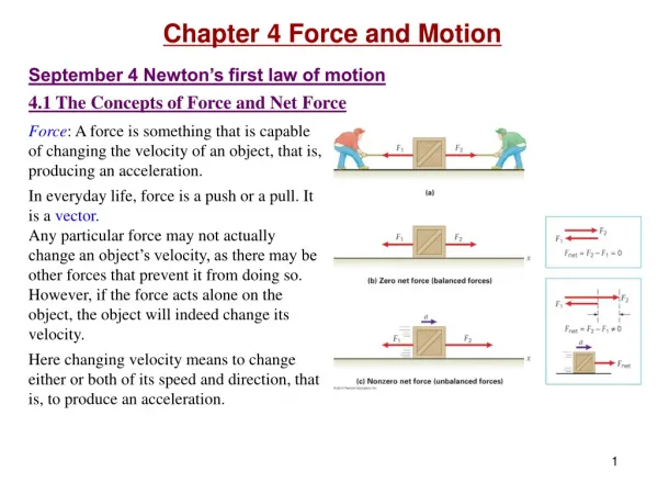
Heat Exchanging & Work Consuming Devices in Power Plants P M V Subbarao Professor Mechanical Engineering Department I I T Delhi Equipment to Create an Efficient Closed Cycle Plant …….
Pearl Street Station Thomas Edison in September 1882 achieved his vision of a full-scale central power station
Steam Wagon/Tractor : Last decade of 19th Century • By 1921, steam tractors had demonstrated clear economic advantages over horse power for heavy hauling and short journeys. • London market roads were free of Horse faeces….
Energy Balance of A Condenser • Energy balance: • The temperature rise of cooling water: • 6 to 7 degree C for single pass. • 7 to 9 degree C for single pass. • 10 to 12 degree C for four pass.
Thermal Processes Occurring in Condensers • The condenser never receives pure seam from the turbine. • A mixture of steam and non-condensable gases (Air-steam mixture) enters the condenser. • The ratio of the quantity of gas that enters the condenser to the quantity of steam is called the relative air content. The value of , depends on type, capacity, load and design dimensions of the condenser plant.
Using Dalon’s Law: Law of Mixtures • Gas laws:
Impact of Non-Condensibles • At the entry to condenser the relative content of air is very low and partial pressure of steam is almost equal to condenser pressure. • As air-steam mixture moves in the condenser, steam is condensed and the relative content of air increases. • Accordingly, the partial pressure of steam drops down. • The pressure in the bottom portion of condenser is lower than that of the top portion. • The pressure drop from inlet to exit of condenser is called steam exhaust resistance of a condenser. The partial pressure of air at the bottom of the condenser cannot be neglected.
Combined Condensation & Air Pumping Action: Air Pumping Action Vs Condensing Action !!!
Air pump controlling the back pressure Condenser controlling the back pressure Air pump controlling the back pressure Condenser controlling the back pressure Effect of Air Leakage on Condenser Pressure Inlet Condenser Pressure, mm of Hg 10 30 40 50 20 Cooling water Inlet Temperature
Power Loss Due to Excess Back Pressure What is Techno-economically Viable value of TTD ?
Condenser Performance • 500MW unit condenser overall heat transfer coefficient obtained from the condenser model is 2947 W/m2 oC. • Value of overall heat transfer coefficient provided by the manufacturer is 2907 W/m2 oC. • Thus representing an error of 1.37% in estimated value of overall heat transfer coefficient.
Effect of Ambient Temperature & Water Flow Rate Cooling Water Flow rate: 36200 Cumecs C
Effect of Ambient Temperature & Water Flow Rate Cooling Water Flow rate: 28800 Cumecs
A Major Crossroad Confusion: How to go from <6% to 75% Efficiency ???????
A Manual of the Steam Engine and Other Prime Movers (1859)William John Macquorn Rankine • This law of the maximum efficiency of heat engines is a particular case of a general law which regulates all transformation of energy, and is the basis of the Science of Energetics.
How about a modified cycle - A Rankine cycle • To avoid transporting and compressing two-phase fluid, try to condense all fluid exiting from the turbine into saturated liquid before compressed it by a pump. • when the saturated vapor enters the turbine, its temperature and pressure decrease and liquid droplets will form by condensation. s • These droplets can produce significant damages to the turbine blades due to corrosion and impact. • One possible solution: superheating the vapor. • It can also increase the thermal efficiency of the cycle.
Power Consuming Turbo-machines An expenditure of earnings….
Pump services in Main Steam Cycle • Turbogenerator and auxiliaries • Condenser circulating pumps • Screen wash-water pumps • Cooling tower make-up pumps • Steam generator equipment • Condensate pumps • Condensate booster pumps • Boiler-feed pumps • Boiler-feed booster pumps • Deaerator make-up pumps • Heater drain pumps (low and high pressure)
Rhyd,2 Rhyd,1 Rhyd,n pOFWH+ploss Expectations from A Condensate Pump Duty: Generate Required Open Feed water Heater Conditions ! Condensate Pump OFWH Hot Well
Rhyd,SG plive steam Rhyd,1 Rhyd,n ploss+plive water Steam Turbine Expectations from A Boiler Feed Pump To Generate Required Live Steam Conditions ! BF Pump OFWH
Cross-section, single 48.5 MW boiler feed pump, 1300 MW fossil power plant
Machine-Fluid Matching Parameter For Pumps For fans
DIMENSIONAL ANALYSIS • Scale model to prototype design and analysis. • Used to select proper turbo-machine (axial, radial or mixed flow,…) • Used to define performance parameters
Matching of a Pump/Fan to A Need Speed: N (rpm) or n (rps) This is named as Specific Speed, Ns
Popular Definitions for Pumps The specific speed, usually represented by Ns, also denominated absolute specific speed or specific angular speed.
SELECTION OF SPEED A pump/fan with a given flow geometry and momentum transfer principle
Selection of Geometry Vs Specific Speed Specific Speed
Specific Speed Vs Flow Geometry& Principle of Momentum Transfer Mixed Axial Flow / Airfoil Action Radial Fow/ Centrifugal Action
Speed Vs Size : Constant Head & Flow Rate Demand Speed nf = 492 rps N=1000 rpm N=1500 rpm N=3000 rpm
Power Losses in Pump • Head losses due to suction and delivery pipe fittings, entrance losses, impeller frictional losses and casing frictional losses. • Power loss due Leakages and recirculating fluid. • Disc Friction loss • Mechanical Losses