Fuel Cell System Integration
This guide provides an in-depth exploration of fuel cell system integration, focusing on synthesis and design decisions. It covers crucial components selection, stack configurations, fuel reformers, and air compressor choices while considering factors such as cost, efficiency, and operational conditions. The document outlines the complexities of integrating stacks with reformers, heat exchangers, and exhaust systems. Key design considerations include operating temperatures, pressures, fuel utilization, and byproduct management, aiming for optimal performance and economic viability in fuel cell systems.

Fuel Cell System Integration
E N D
Presentation Transcript
Synthesis and Design • Synthesis – determine the components to use and their relationship to each other • Design – determine the conditions at which the various components will operate
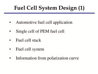
FC System Synthesis Decisions • Fuel cell type • Choices – PEMFC, DMFC, PAFC, MCFC, SOFC • Factors to consider - cost, efficiency, operating temperature, available fuel • Fuel cell stack configuration • Number and size of cells • Cooling design • Assembly of cells into stacks or sub-stacks • Fuel reformer • Type of reformer • Choices - Steam reforming, partial oxidation, autothermal • Factors to consider - Source fuel, desired exit gas composition, efficiency vs. complexity, weight, cost, etc. • Reformate clean-up components • Choices – shift reactors, PROX, membrane separation, PSA • Factors to consider – cost, efficiency, desired composition
FC System Synthesis Decisions (continued) • Integration of stack and reformer – external, internal indirect, internal direct • Air compressor - compressor type (screw or centrifugal), intercooler • Heat exchanger network – type, location • Exit gas components – condensers, turboexpanders, heat exchangers • Bottoming cycle equipment • Gas turbine • Steam power cycle
Higher first cost Higher efficiency Lower operating cost V Lower first cost Lower efficiency Higher operating cost i FC Design Decisions - Voltage • Stack operating voltage
FC Design Decisions - Pressure • Higher operating pressure yields • Increased reactant concentration – increased electrochemical kinetics; higher Nernst voltage • Higher efficiency and/or current density • Reduced system size • Reduced humidification requirements • Higher parasitic power requirements • Higher likelihood of soot formation in reformer • Reduced degree of reaction for steam reforming • Higher corrosion rates at cathode (MCFC)
FC Design Decisions - Utilization • Higher fuel utilization (lower equivalence ratio) yields • Reduced fuel use within the stack • Reduced fuel processing system size, cost • Lower cell voltage • Higher stack cost • Less exit gas for application in bottoming cycle • Higher oxidant utilization (lower equivalence ratio) yields • Reduced compressor power • Reduced air system size, cost • Reduced humidification requirements • Lower cell voltage • Higher stack cost
FC Design Decisions – Temperature • Higher operating temperature yields • Increased operating voltage • More flexible thermal integration • Less exotic catalyst and resistance to poisoning • Higher quality rejected heat • Increased corrosion potential (especially PAFC, MCFC) • Longer warm-up and higher thermal stress • Increased complexity
FC Design Decisions – Etc. • Higher reactant humidification yields • Higher cell voltage (PEMFC) • Higher resistance to carbon formation in reformed fuels • Increased cost of water (or equipment to condense from exit stream) • Increased capital cost and complexity • Potential for flooding • Increased size (and number) of heat exchangers yields • Improved quality and quantity of thermal energy available • Better system integration possibly improving overall electrical efficiency • Increased cost