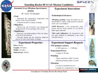
Non-Maxwellian Plasma Observations in Bottom-Type Scattering Layer Before Equatorial Spread F
30 likes | 212 Vues
This study presents findings from the NASA EQUIS II campaign, focusing on the non-Maxwellian plasma observed in the bottom-side of the equatorial F-region ionosphere. Two sounding rockets were launched from Roi Namur in August 2004, employing various probing instruments to capture electron energy distributions. Analysis revealed significant electron density variations and potential measurement errors due to skin effect interactions. The data supports a deeper understanding of payload charging and electron dynamics in equatorial spreading F phenomena.

Non-Maxwellian Plasma Observations in Bottom-Type Scattering Layer Before Equatorial Spread F
E N D
Presentation Transcript
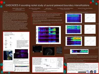
Observations of non-maxwellian plasma in the bottom-type scattering layer precursor to equatorial spread F Aroh Barjatya, arohb@cc.usu.edu Dr. Charles M. Swenson, Charles.Swenson@usu.edu Dr. David Hysell, dlh37@cornell.edu I. Sounding Rocket Mission Overview III. Understanding Payload Charging Through Simulations V. Flight Data Abstract: The rocket investigation “Scattering Layer in the Bottomside Equatorial F-region Ionosphere” was part of the NASA EQUIS II campaign. Two salvos of sounding rockets were launched from Roi Namur in Kwajalein on August 7th and 15th of 2004. Each of the salvos consisted of one instrumented and two chemical release payloads. The instrumented rockets were launched westward into equatorial spread F precursor that was first observed from ground using the Altair radar. The instrumented rockets reached an apogee of ~421 km. The instruments consisted of an internally heated Sweeping Langmuir Probe, a fixed bias DC Langmuir Probe, a Plasma Impedance Probe consisting of a Plasma Frequency Probe and a Plasma Sweeping Probe built at Utah State University. The instrument suite also included an Electric Field Probe built by Penn State University. We use the SLP sweep from –1 V to +5 V to derive Electron Energy Distribution Functions (EEDF) which show the presence of non-Maxwellian plasma in the spread F precursor. Due to a small ‘skin to probe’ area ratio, as the SLP sweeps to higher voltages the payload reference potential goes negative to counter the additional electron current accumulated by the SLP [5]. Figure 3 shows how the –1 to 5 V sweep of the SLP w.r.t. the rocket skin (i.e. V(3)-V(1)), is warped and shifted w.r.t. the plasma (i.e. V(3)). The warping results in an overestimation of the electron temperature and the shifting results in an error in density determination. The rocket skin channel (inverse of V(1)–V(2)) records the voltage difference between one of the EFP spheres and the payload skin. Figure 3 also shows how one of the skin channels varies as the SLP sweeps. Figure 4 shows the current as observed by the SLP and DCP. Figure 10Electron Density Profiles Both rocket flights were around 9 pm local time. The relative densities derived from the quasi-DC observed current of the SLP are as shown in Figure 10. These have been normalized at 350 KM (29.036) and 320 KM (29.037) to the PFP observed absolute density. Figure 3Model SLP voltage sweep and apparent skin potential Figure 4Model Current as observed by SLP and DCP Figure 11 shows the skin channel voltage during two consecutive sweeps at an altitude of 375 Km on upleg. The skin channels were sampled at 1/110 the rate of the SLP and thus we do a spline fit to the data to approximate the warped portion of the skin floating potential. Figure 12 shows SLP observed current. It is not apparent in figures 3 and 4 if there is any hysteresis associated with the SLP voltage sweep in the SLP current and skin voltage channel. This hysteresis is more clearly apparent in figures 5 and 6. Although SLP was internally heated and cleaned, the rocket skin was not and the rocket skin contamination appears to be the cause of this hysteresis. Figure 1 The rocket and payload configuration The instrumented rockets were launched westward into equatorial spread F precursor that was first observed from ground using the Altair radar. The instrumented rockets reached an apogee of ~421 km. ACS was used to align the payload axis with the magnetic field. Figure 1 shows a representation of the payload. Figure 12 Hysteresis in SLP sweep data Figure 11Hysteresis in skin channel data Figure 5Hysteresis in model Skin voltage channel Figure 6Hysteresis in model SLP current Comparing the flight data with simulation results we see that the skin channel observed more hysteresis and yet the amplitude of warping recorded is very less. Upon taking an EEDF of this data we see results similar to figure 8 indicating that the skin channel data did not represent the warping accurately. This could be either due to excess contamination on spheres/rocket skin or due to onboard filtering of skin channel data. We thus discard the first few millivolts of the electron retarding region and generate the EEDF using the rest of the data. The EEDF shown in figure 13 and affirms the distribution to be maxwellian. • The instrument suite on payload included: • Internally heated cylindrical Sweeping Langmuir Probe (SLP) to measure electron temperature. The sweep went from -1 to +5 volts. The probe was guarded on one side. • A fixed bias (+3V) DC Langmuir probe (DCP) to measure relative electron density. • Plasma Impedance Probe (PIP), consisting of Plasma Sweeping Probe (PSP) and Plasma Frequency • Probe (PFP), to measure absolute electron density. • Electric Field Probes (EFP). IV. Electron Energy Distribution Function An Electron Energy Distribution Function (EEDF) can be generated from the SLP sweep data using the Druyvesteyn formula [4]. We then compare it with a maxwellian distribution. Druyvesteyn formula Maxwellian distribution Figure 13 EEDF of flight data II. Payload Circuit Model The density and temperature are derived from EEDF using : We do a similar analysis for data at 275 km where the density and E-field data indicate the presence of irregularities [7]. The current sweeps are depicted in figure 14 and the derived EEDF is depicted in figure 15. The two humps in EEDF hint towards a non-maxwellian distribution. We use SPICE to model the payload and get a qualitative insight into payload charging and its effect on instrument behaviour[1]. The circuit model of the rocket skin and the probes is as shown in figure 2. Plasma potential is taken as 0 V. The rocket skin is numbered as node 1, EFP as node 2, SLP as node 3 and DCP as node 4. Each current collecting surface also included contamination related capacitance and resistance with the exception of SLP (which was internally heated) [2][3]. The sheath capacitance and resistance are much smaller and insignificant in comparison with contamination capacitance and resistance, and thus have not been included. The rocket skin, SLP, and DCP were modeled as cylindrical probes and the EFP as a spherical probe [4]. The contamination capacitance for the rocket skin was set at 100 F, and for the DCP at 1 F. The contamination resistance was set at 1 K for rocket skin and at 10 K for the DCP. The ratio of the payload skin area to that of the cumulative surface area of the active probes was ~120 and is modeled accurately to with in 10% in the simulation. To illustrate the process, we calculate the EEDF for the simulation using the SLP observed total (ion+electron) current [6] with the applied voltage (w.r.t. plasma) at each step calculated by adding skin channel voltage to sweep voltage (w.r.t. skin). We then plot a maxwellian distribution using the plasma parameters derived from the EEDF. The plots are shown in figure 7. As the current model used in the simulation was maxwellian, the EEDF resembles a maxwellian distribution. It is imperative that the voltage used in the second derivative in Druyvesteyn formula should be that of the probe w.r.t. plasma. This point is illustrated in figure 8 where the second derivative was taken using the sweep voltage of -1 to 5 volts w.r.t. skin. The EEDF does not resemble a maxwellian and the derived plasma parameters are not correct. Noting that the warping of the surface potential starts slightly before the SLP current hits the knee, we discard the data for the first few hundreds of millivolts in the retarding region and then compute the EEDF for the remainder of the sweep. The EEDF thus derived is shown in figure 9 and is maxwellian although the derived density is less then the actual density. Figure 14 Low altitude SLP sweep data Figure 15 EEDF of flight data Summary and Future Work: This work has simulated a sounding rocket payload with a significantly low ‘probe to skin’ area ratio, in addition to surface contamination, and noted resultant effects on collected data. The problems associated with deriving EEDF when the probe to plasma potential is not known are also illustrated. We have then analyzed the flight data in two different altitude regions. While at high altitudes the plasma is observed to be maxwellian, the low altitude data where irregularities are indicated by other datasets appears to be non-maxwellian. As the probe to plasma potential is not accurately known and the signal to noise ratio is also poor in the low altitude region, fitting for various non-maxwellian distributions becomes challenging but will be our future effort. References [1] Barjatya, A., and C.M.Swenson, Observations of vehicle charging in dusty plasma, 8th Spacecraft Charging Technology Conference, Huntsville, Alabama, Oct 2003. [2] Oyama, K-I (1976), A systematic investigation of several phenomena associated with contaminated langmuir probes, Planet. Space Sci., 24, 183 . [3] Piel, A., M. Hirt, and C.T. Steigies (2001), Plasma diagnostics with Langmuir probes in the equatorial ionosphere: I. The influence of surface contamination, J. Phys. D: Appl. Phys., 34, 2643 [4] Lieberman and Lichtenberg (2005), Principles of Plasma Discharges and Materials Processing, 2nd ed., John Wiley and Sons, New Jersey. [5] Szuszczewicz, E. P. (1972), Area influences and floating potentials in Langmuir probe measurements, J. Appl. Phys., Vol 43, No. 3. [6] Sudit and Woods (1993), A workstation based Langmuir probe system for low-pressure dc plasma, Rev. Sci. Instrum., Vol 64, No.9. [7] Hysell et. al, Onset conditions for equatorial spread F determined during EQUIS II, submitted to Annales Geophysicae in 2005. Figure 7 Sweep voltage used w.r.t. plasma Figure 8 Sweep voltage used w.r.t. skin Figure 9 Sweep voltage used w.r.t. skin First 0.25 volts of retarding region discarded Figure 3 Rocket and probes electrical model