Download
1 / 4
40 likes | 120 Vues
Learn how the GRID Data Center at INFN Pisa enhances HEP analysis activities with robust storage, CPU resources, and top-notch infrastructure, supporting diverse research tasks efficiently.

E N D
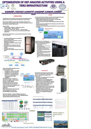
Optimization of HEP Analysis activities using a Tier2 Infrastructure G.Bagliesia, T.Boccalia, S.Coscettib, E.Mazzonia, S.Sarkarc, S.Tanejad a: INFN Sezione di Pisa, Pisa, ITALY, b: ScuolaNormaleSuperiore, Pisa, ITALY, c: Saha Institute, Kolkota, INDIA, d: S.Taneja, DipArtimento di Informatica, Pisa, ITALY • INTRODUCTION • The GRID Data Center at INFN Pisa hosts a big Tier2 for the CMS experiment, together with local usage from other HEP related/not related activities • The Tier2 has to fulfill on one side a series of activities mandatory in the Memorandum of Understanding of CMS, on the other side support as much as possible Italian Physicists doing research • Typical activities • MC prod (MoU): ~1000 cores, 50 TB temporary space • Analysis via GRID: ~1000 cores, 800 TB • Local analysis: ~50 users LSF ~ 500 cores, ~ 100 TB local space • Interactive work: ~50 users, few cores each (mostly multi threaded applications) • There are three ingredients to a successful large scale data center: storage, CPUs, infrastructure • Storage • A center used for diverse activities must offer a solid storage infrastructure, accessible through all the protocols needed by the use cases • SRM for WAN organized transfers (we use Storm, an italian SRM implementation, and dCache for legacy files) • At least one protocol for locally running GRID jobs (we offer dCap, POSIX, XrootD) • At least one protocol for WAN direct (streaming) access (we offer XrootD both from dCache and Storm) • Interactive users in the end always prefer POSIX direct access (we offer that on Storm) • 2 DataDirect DDN9900 systems, with 300 disks each ( >1 PB raw storage) • Total of 4x8 8 Gbit/s FC connections, served to GPFS NSD via a FC Switch • 8 GPFS NSD with MultiPath enabled, 10 Gbits connectivity • GPFS version 3.4.0, serving more than 1 PB • DDN EF3015 storage dedicated to Metadata handling • DataDirect 12k on arrival • Throughput from storage measured in excess of 32 Gbit/s • CPU • The GRID data center in Pisa (~5000 cores) is engineered to make sure that the biggest number of tasks is running at any time, which means • No jobs are guaranteed to run instantaneously • Every user/group of users can in principle saturate the whole farm • We are happy to host GRID jobs from users from experiments not present in Pisa • No restriction is imposed to jobs when the farm is not full • In case of multiple queued jobs, a fairshare is implemented via LSF which matches the share of resources • Only case in which some resources are left unused is a small part of the cluster (~500 cores) which can be preempted by parallel jobs • Infrastructure • The Pisa Data Center largely exceeds the typical dimension of a Department’s computing center. As such, it is equipped with enterprise level infrastructure • Rack space: the computing room can host up to 34full height standard racks. • Networking: we use a flat switching matrix, implemented via a Force10 E1200 fabric. It allows for a point-to-point 1Gbit/s (or 10Gbit/s) connection between all the machines. We use 1Gbit/s on all the Computing nodes, and 10Gbit/s on all the storage nodes. • Electrical distribution: we are served with a 300 KVA connection. All the services, and part of the Computing nodes, are served by UPS. • Cooling: the computing room is served by 12 APC InRow air sources, cooled by 3 Emerson Chillers on the roof (300 kW refrigerating capacity) • Users need specific machines to carry on their research work • Possibility to submit to the GRID • Possibility to use the local farm • Possibility to run interactively a process on a single/multi cores with guarantees on RAM availability • We decided to have a number of machines available, using the batch system as a load balancer. • The batch system directs you to a machine where you have the # of cores and memory you asked for, and • makes sure no other task is interfering. • When the interactive load is low, the same machines can be used as standard GRID processing nodes Force10E1200 Request 4 interactive cores in the UI cluster We had to develop a number of Monitoring tools to make sure the site is operational. These complement the standard CMS and WLCG existing tools. APC InRow LSFMon Netvibes widgets to monitor dCache, LSF Infrastructure status Partially developed under PRIN 2008MHENNA MIUR Project
Optimization of HEP Analysis activities using a Tier2 Infrastructure authors Another Site WAN Transfers Remote UI Remote UI GRID jobsubmission XrootD Remote file access via streaming SRM PISA Disk CPU Job overflowto UIs PISA Local jobsubmission Disk dCap Local fileaccess XrootD Posix CPU Local UI cluster LSF Frontend machine LAN Transfers PRIN statement
Remote UI Remote UI GRID jobsubmission Remote file access via streaming PISA Disk CPU Job overflowto UIs Local jobsubmission Local fileaccess Local UI cluster LSF Frontend machine Another Site WAN Transfers XrootD PISA Disk SRM dCap XrootD Posix CPU LAN Transfers