Download
1 / 102
1.05k likes | 1.56k Vues
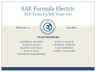
SAE Formula Electric ECE Team #3/ME Team #21. Milestone: 4. Test Plan. Aldreya Acosta Tomas Bacci Danny Covyeau Scott Hill Stephen Kempinski Ryan Luback George Nimick SAM Risberg Corey Souders. TEAM MEMBERS:. Top Level Electrical System. Presented by: DANNY cOVYEAU.

E N D
SAE Formula ElectricECE Team #3/ME Team #21 Milestone: 4 Test Plan Aldreya Acosta Tomas Bacci Danny Covyeau Scott Hill Stephen Kempinski Ryan Luback George Nimick SAM Risberg Corey Souders TEAM MEMBERS:
Top Level Electrical System Presented by: DANNY cOVYEAU
Agni 95-R Motor Peak Efficiency: 93% Constant Torque: 42 Nm Continuous Output Power: 22 kW Weight: 24 lbs Popular, dependable choice among Formula Hybrid teams Danny Covyeau
Kelly KD72501 Motor Controller • Optical Isolated: • throttle potentiometer • brake potentiometer • switches • Uses high power MOSFETs to achieve ~99% efficiency • 200 Amps continuous • 500 Amp peak for 1 minute • Built in regenerative braking that can recapture up to 100 amps • Still requires mechanical brakes • Programmable controller with a user-friendly GUI * Courtesy Kelly KD User Manual Danny Covyeau
Motor & Controller Testing Objective: Verify that the electric motor controller works properly by testing that the forward and reverse functions of the motor operate Desired Result: The controller will be able to accelerate in both the forward and reverse directions Status: Controller has not been able to be programmed due to frequent resetting and under voltage warnings Next Step: Use a more powerful power supply (~80 VDC) to eliminate under voltage warnings and attempt to eliminate frequent resetting. Once the controller can be programmed the motor will be wired up. Danny Covyeau
Controller Contingency Plan(s) • Kelly KDH07501A - $599 • Optically isolated • 24 – 72 VDC, 500A with Regen • Kelly KDH12601E - $999 • Optically isolated • 12 – 120 VDC, 600A with Regen • Both controllers eliminate the need for the isolation circuit Danny Covyeau
Optoisolator Circuit Testing • Objectives: • The LV and HV grounds have a minimum resistance of 40,000 ohms between them • The output voltage of the circuit corresponds linearly with the input voltage of the circuit • Test Plan: • Use a low voltage variable DC power supply and a voltmeter to test the optoisolator circuit will be built. • Desired Result: • The input and output voltage of the throttle should vary from zero to five volts linearly. Danny Covyeau
Speedometer Testing • Calibrated Using Sine Wave Generator • Requires at least 500 pulses per mile from a Hall Effect Sensor • Status: • Tested Successfully Danny Covyeau
Potbox Testing • Objective: • To verify the proper operation of the throttle potentiometer (potbox). • Test Plan: • Attach potbox to 5 VDC power supply and verify that the output ranges between 0 and 5 volts using a voltmeter • Desired Result: • The potbox is expected to act as a simple voltage divider and deliver voltage levels that range from zero to five volts. • The potbox must deliver a range of voltages between zero and five volts to be considered functional. Danny Covyeau
Battery System, BMS, Other electrical components Presented by: Scott Hill
Major Design Changes in Battery System • The following issues occurred in the ordering process of the batteries: • Company (hobbyking.com) did not accept purchase orders and it was hard to communicate with them • The team tried to order the batteries through a local hobby store and the markup was higher than the seller told us it would be so it was rejected. • Two members of the team attempted to order the batteries themselves and be reimbursed. By the time the orders had been placed the batteries were on backorder and would be for about a month Scott Hill
Major Design Changes in Battery System (Cont.) • When the team found out that the batteries had been placed on backorder it was around late January and the timeframe of waiting on the backorder and shipping was not acceptable. • Alternatives were looked at through local retailers Battery Source and Fouraker Electronics. • Both companies could order through powersonic.com Scott Hill
Battery Types Available • Lead Acid ( Various types) • Pros: Low Price, Simple BMS needs, higher voltages easily obtained, longer lifetime than Li-Po • Cons: More weight, lower discharge than desired • Nickel-Metal Hydride • Pros: Less weight, lower price than Li-Po batteries • Cons: Lower voltage (more batteries required), lower discharge than desired Scott Hill
New Battery Configuration After looking at powersonic’s website a high rate series lead acid battery was found. Taking the higher weight into consideration and running the MATLAB simulation with the new estimated weight the team decided to go with a 36Ah battery. Scott Hill
Battery Specs PHR-12150 High Rate Series Scott Hill
BMS Changes • BMS Requirements • Li-Po Design • Temperature monitoring per module • Voltage monitoring per cell • Lead Acid Design • Temperature monitoring per module • Benefits of Lead Acid Configuration • Since there are only 6 batteries less monitoring is needed • Voltage monitoring is not required like with the Li-Po batteries Scott Hill
New Battery System and BMS schematic Scott Hill
Ground Fault Detection Scott Hill
Ground Fault Detection Circuit Add GFD circuit here Scott Hill
Battery System and BMS Test Plan • Things to be tested • Individual battery characteristics such as discharge characteristics, capacity and voltage will be tested. • BMS circuit will be tested to make sure that if the temperature of the lead acid batteries gets too high then the system will automatically shut off. • Ground fault detection circuit needs to be tested to make sure if a short occurs between the HV and LV circuits the system will be shut off. Scott Hill
Top Level Mechanical System Presented by: George Nimick
Chassis Presented by: George Nimick
Chassis Design – Approach • Purpose • Structural Barrier • Debris and accidents • Enclosure • Incorporation of a body • Platform for mounting systems • Steering, Braking, Suspension, Propulsion, Driver Equipment George Nimick
Chassis – Material Selection • Major types: • Monocoque • Tubular • Metal • Steel • 1018 vs. 4130 • Restrictions based on rules • Angles • Distances • Wall thicknesses George Nimick
Chassis - Calculations • Bending Stiffness • Proportional to E*I • Primarily based on I • Bending Strength • Given by • Compare to requirements in rules George Nimick
Chassis – Tubing Specifications George Nimick
Chassis - Restrictions Template for Cock-pit Opening Template for Cross-Sectional Area Roll Hoop Restrictions George Nimick
Chassis George Nimick
Chassis – Test Plan 1 George Nimick
Chassis – Test Plan 2 George Nimick
Chassis George Nimick
Chassis George Nimick
Chassis • Jig fabrication • Placement sketched • Blocks screwed into position • Members cut and placed George Nimick
Chassis George Nimick
Chassis George Nimick
Chassis George Nimick
FEA Tests Performed • Finite Element Analysis • Difficult to perform and properly assess • Tests performed • Front Impact • Rear Impact • Side Impact • Full Suspension Loading • Single Side Loading for suspension George Nimick
Front Impact - Worst Stress George Nimick
Front Impact - Displacement George Nimick
Full Suspension Test Displays Displacement Magnitude Displays Worst Stresses George Nimick
Suspension Presented by: Stephen Kempinski
What’s to come Brief overview Current progress Deadline Test plan Stephen Kempinski
Competition Constraints 3.2.1 Suspension fully operational suspension system with shock absorbers, front and rear usable wheel travel of at least 50.8 mm (2 inches), 25.4 mm (1 inch) jounce and 25.4 mm (1 inch) rebound, with driver seated. 3.2.2 Ground Clearance with the driver aboard there must be a minimum of 25.4 mm (1 inch) of static ground clearance under the complete car at all times. Stephen Kempinski
Competition Constraints Continued 3.2.3 Wheels and Tires 3.2.3.1 Wheels The wheels of the car must be 203.2 mm (8.0 inches) or more in diameter. 3.2.3.2 Tires Vehicles may have two types of tires as follows: Dry Tires – The tires on the vehicle when it is presented for technical inspection are defined as its “Dry Tires”. The dry tires may be any size or type. They may be slicks or treaded. Rain Tires – Rain tires may be any size or type of treaded or grooved tire provided: Stephen Kempinski
Suspension Design Overview Independent Short-Long Arm Push-rod • Better ride quality • Improved handling • fully adjustable • Short Long Arm Suspension • Lower A-Arm is longer than the Upper A-Arm • Reduced changes in camber angles • Reduces tire wear • Increases contact patch for improved traction Stephen Kempinski
Design Method Determine Wheel-Base, Track-Width Design for FVSA Design for SVSA Stephen Kempinski
Suspension Layout Compromise between chassis and suspension design Averaged from well scoring FSAE teams Stephen Kempinski
FVSA Static case Instant center location Roll instant center location FVSA length Stephen Kempinski