HOUSEKEEPING HK at Balloon-EUSO
320 likes | 433 Vues
This document presents the housekeeping (HK) design for the EUSO-Balloon project discussed during the 10th JEM-EUSO meeting held from December 5-10 at RIKEN, Tokyo. The design focuses on a Low Voltage Power Distribution System (LVPDS) utilizing an Arduino Mega 2560 for monitoring and control. It details the power supply connections, requirements, and system specifications, including a prototype Power Supply Board (PSB) for efficient voltage regulation. Key considerations for development timelines and subsystem feasibility are also addressed.

HOUSEKEEPING HK at Balloon-EUSO
E N D
Presentation Transcript
HOUSEKEEPING HK at Balloon-EUSO 10th JEM-EUSO meeting from December 5th to 10th at RIKEN, Tokyo By G. Medina-Tanco*, A. Zamora, L. Santiago Cruz**, F. Trillaud**, and H. Silva***. *Institue of Nuclear Science, National Autonomous University of México. **Institute of Engineering, National Autonomous University of México. *** Ebizusaki Computational Astrophysics Laboratory, RIKEN. December 7th, 2011.
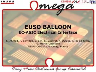
24V 24V 24V to 12V DDCU Housekeepingdesignbasedon LVPS Board at EUSO-Balloon 24V to 15V DDCU 24V to 5V DDCU 24V to 5V DDCU
Conceptual drawing of HK in the case whichtheonly interfaces are PSB and CNES. PowerSupplyBoard SignalConditioning & Command drivers Auduino Mega & Protocols
Conceptual drawing of HK forthemost general scenario, in whichthere are interfaces with PSB, HV, CCB and CNES.
Thenumber of availableanalog and digital channels in ArduinoBoard are more thanenoughtomeetall TM&TC requirements. But NOTE! That interfaces with HV, CCB and CNES are notfullydefined. 44 44 2 2 4
Finally, someimportantcomments… • TheArduino Mega 2560 option, couldbedelivered in earlyApril 2012, whereasthebaselinedesignwouldbecompletedaroundmid August2012. • TheArduino Mega 2560 doesnot use FPGA, in consequenceitisverylikelythatcouldnotbeused as final prototypefor JEM-EUSO. • Isnecessaryto define thesubsystemrequirements in ordertoevaluatethefeasibility of Arduino Mega 2560 optionfor HK at EUSO-Balloonproject.
Low Voltage Power Distribution System(LVPDS) at Balloon-EUSO PSB 1st prototype • 10th JEM-EUSO meeting • from December 5th to 10th • at RIKEN, Tokyo By H. Silva***, G. Medina-Tanco*, A. Zamora, L. Santiago Cruz**, M. Casolino***, and K. Tsuno***. *Institue of Nuclear Science, National Autonomous University of México. **Institute of Engineering, National Autonomous University of México. *** Ebizusaki Computational Astrophysics Laboratory, RIKEN. December 7th, 2011.
As a first approach of PDMLVPS • A Power Supply Board (PSB) has been developed in México. • HVPS subsystem was based on EMCO regulator. OUR PROTOTYPE PSB 5V +12V
The interaction with PDMB requires • The PDM board receives 5V and 12V from PDMLVPS. • 5V is used to produce 1.5V, 3.0V and 3.3V. Meanwhile 12V is needed for EMCO circuit section. • There are 9 regulators (final version) • 3V output regulator for ASIC (3) • 1.5V output regulator for ASIC (3) • 3.3V output regulator for FPGA • 1.5V output regulator for FPGA • 0-10V output regulator for HV chip • If HVPS circuit is based on a EMCO module. One EMCO per EC consumption is 0.5W (9EC→4.5W). • HV system current consumption is ~400mA. • If HVPS circuit is based on CW the power consumption from 28V (instead 12V) is 55mW per EC (9EC→495mW). However, external control consumption is missing. • FPGA consumption is 1W~2W. • PDMB Total power consumption is ~4W. • Interface power connector used is 9pin D-sub. PDM board From a power board InformationprovidedbyAera ASIC
PSB description • Is based on three MURATA isolated DC-DC converter. • 5V for PDM, 12V for HV generation chips and 5V HK monitor circuits. 182mm X 95mm 24V bus voltage V&I monitoring circuits • UEI15-120-Q12P-C 12V/1.3A • UEI15-050-Q12P-C 5V/3A • MEV1S2405SC 5V/0.2A
PSB-HK TM/TC interface electrical specs Monitored Output Voltage levels: • A DB15 connector is proposed for transmitting voltage signals * Design calculations values NOTE! Voltage levels measured on PCB TBC
PSB-HK TM/TC interface electrical specs Monitored Output Current levels: PIN_RET_12V PIN_RET_5V RET_12V RET_5V • A DB15 connector is proposed for transmitting voltage signals * Design calculations values NOTE! Voltage levels measured on PCB TBC
PSB Bread board Model (BM) tests Upper left, voltage converters. Upper right, current monitoring circuitry. Lower left, combined view. Lower right, combined tests.
PSB Bread board Model (BM) tests LED lighted, a command has been sent by the Arduino Mega. SetupfortheHL_Cmdtests. A programis uploadedonthe chip of theArduino Mega whichsendstheappropriatecommands.
PSB Bread board Model (BM) tests Tests of the entire PSB on bread-board for passive load. Picture of the active load setup.
PSB Bread board Model (BM) tests Final printedcircuit and tests of the PSB withpassive and active loads.
PSB-PDM interface electrical specs • PSB – PDM Interface power connector is based on a 9pin D-sub right angle. • The proposal is a MDM connector approved by MIL-DTL-83513.
PSB TM/TC interface proposal PSB • The PSB latching relay receives two HL_cmd from CNES. • Voltage and current monitoring circuits will provide floating signals to HK board by DB15 connector. • Analog multiplexers and ADC are used for reading voltage digital value in programmable device. • A serial line driver is foreseen in HK board for sending TM to CNES. • HK has relay turn-on capability through open drain commands and also acquisition CC (their use is TBC). • Temperature monitoring circuit could be implemented according to requirements.
Low Voltage Power Distribution System(LVPDS) at Balloon-EUSO Actual Status • 10th JEM-EUSO meeting • from December 5th to 10th • at RIKEN, Tokyo By H. Silva***, G. Medina-Tanco*, M. Casolino***, and K. Tsuno***. *Institue of Nuclear Science, National Autonomous University of México. **Institute of Engineering, National Autonomous University of México. *** Ebizusaki Computational Astrophysics Laboratory, RIKEN. December 7th, 2011.
So far now LVPDS interacts with… • CNES: At the moment CNES (or someone) will provide an On/Off command to a Latching Relay (LR) • and LVPD will replay with contact closure (CC) • signal. • PDM: This structure requires power supply lines for HVPS • board and PDMB internal circuitry. • DP: This structure requires power supply levels for at least • three subsystems: HK, CCB and CPU. Clock (CLK), Data storage (DST) and IR camera (IR-CAM) blocks is TBC.
LVPDS Requirements • The LVPS shall supply power to PDM and DP modules. • The LVPS shall consist in two different power distribution modules, PDMLVPS and • DPLVPS. • PDMLVPS and DPLVPS shall provide isolation interface between 28V bus PWP and all • subsystems. • - The isolation stage will comprise isolated DDCUs with efficiencies higher than 80%. • The regulation stage shall be performed directly at load (as close as possible) for best • performance. • The regulation stage will comprise isolated niPOL converters with efficiencies higher • than 90%. • Propagation failures inside of LVPS modules should be controlled. If any failure event • occur cannot be propagated to PWP and subsystems. • The LVPS modules shall provide ON/OFF functionality in order to be controlled from OB- • SIREN. • The DDCUs shall provide low input voltage protection function to avoid malfunctions at • low input voltage. • The DDCUs shall provide input circuit protection function in order to protect circuit at • secondary side when over current flows to input by some abnormalities. • - The DDCUs shall provide output over current protection function. • - Input and Output EMI filters should be consider in design LVPS modules. • - The LVPS subsystem reliability is TBD. • - The maximum PCB dimensions shall match with PDM size structure.
LVPDS Environmental Requirements • The LVPS elements must endure environmental variability within industrial temperature ranges (-40°C to 85°C). • - The LVPS elements must withstand shock acceleration levels of at least 15 G. • - The LVPS elements must endure humidity environment conditions of TBD. LVPDS TM&TC Requirements • - The PDMLVPS and DPLVPS modules shall turned On/Off by two HLCMDS. • - The LVPDS modules shall provide On/Off status by CC signal. • The LVPDS modules shall provide TM information about voltage and current • levels to HK system. • - TM & TC format information is TBD.
The interaction with CCB requires • The CCB board needs 1.2V for FPGA core, 2.5V as auxiliary voltage and 3.3V for I/O banks. • The current baseline still in 1CCB to serve 8PDM’s. • The estimated power consumption regarding operations modes is: • Normal operation power consumption is 8.5W. • Voltage levels absolute max ratings 1.2V(1.32V), 2.5V(3V) and 3.3V(3.75V). • Voltage levels tolerance 1.2(±5%), 2.5(±5%) and 3.3(±5%). InformationprovidedbyJörg
The interaction with HK requires • The HK board needs ±15V and 5V voltage levels. • ±15V is used for signal conditioning circuit (MUX, ADC, Inst Amp and HL_cmd driver). • The 5V level is used for: • Op-Amp for CC (contact closure) signal. • Buffer interface with PC port. • Also ADC digital part. • The Arduino Mega 2560 control board power consumption is about 1.8W. • The HK board total power consumption expected is about 3W. • In principle, HK will monitor current and voltage levels from power LVPS. • HK use a High efficiency buck switching regulator to provide 5V level.
Other interactions are: • The power consumption expected from CPU module is 12W, and 12V voltage level. • The power consumption of CLK is about 1W at 5V. • The IRCAM supply line is not defined yet. In principle, there are three options: • CPU USB interface. • PWP. • LVPS board. • Power interfaces ?.
The proposal for DPLVPS • CPU in principle could be request 12V voltage line at input with power consumption of 12W. • Meanwhile, CLK part will require 5V at the input with 1W power consumption. • Power supply for IRCAM is TBD.