Download
1 / 33
330 likes | 355 Vues
This article explores the technical aspects of geodynamical measurements using Virgo interferometers. It discusses the accuracy limits of strain and tilts and the sensing of pure gravity field variations. It also examines the possibility of measuring Earth core movements with Virgo.

E N D
Measurement of Geophysical Effectswith large scale gravitational interferometers V.N.RudenkoSternberg Astronomical Institute, MSU Part II : Technical aspects geodynamical measurements with Virgo GGD Workshop 17-18 April 2012, IPGP, Paris (France)
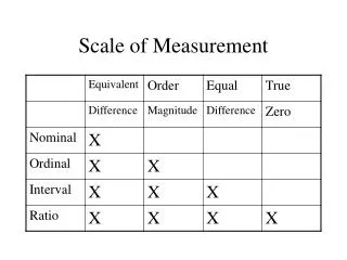
Virgo accuracy limits strainL/L < 10^-16 tilts < 10^-13 rad inner core oscillation effect • Polar mode (а = 1м) 5·10^-14 rad (theory) • Translation mode 5·10^-15 rad (measurement)
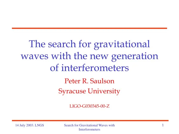
Can we measure Earth Core Movements with Virgo? Virgo Mirrors are suspended with a single wire suspension, hence angle α+β is independent from ground tilt and from Laser beam angle γ. γ L Laser α β If α,β>10-11rad, Δy>1m R δy
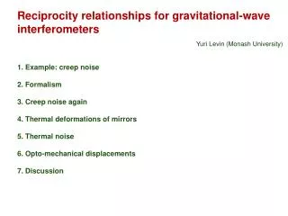
gart DF, g2 g1 b a DF DF GM b GM a g FM EM n IB GM g laser Principle diagram of tilt ground compensation ground GM – guide mirrors FM – front mirror, EM – end mirror DF – driver force IB – injection bench g – tilt deformation gravitational signal !
Conception of angular measurements (Virgo as angular gravity meter) Laser is not suspended: so land angular deformations (tilts of the norm vector) are transferred to beam deflections ; also there are artificial beam inclinations to lock its position in the mirror’s center ; - all together it composes an “angular noise of the beam” contaminating the gravity plumb line variations. A. Measurement of the “sum of internal angles” composed by beam with front and end mirrors filters the “angular noise of the beam”, so again the plumb lines are affected only by gravity force variations - B. Measurement of a single angle “beam ^plumb line” presents the principle of conventional tilt meter: variations of the gravity force vector can be measured only at the beam deformational angular noise background; one has to find an additional ability to reduce this noise.
Raw strain data from “inverted pendulum” LVDT sensors were processed by LSM-fitting with theoretical tidal curve. It results in estimations of f - virgo transform (scale) factor, - delay time (phase shift), l – deform. shift (“lock to lock”) Virgo strain data
Theoretical curve , experimental curve (raw data) and drift curve for North arm during 13 days VSR-2
Sun diurnal S1: 1440 min, 1.1574e-5 Hz (+P1+…sK1,mK1) Moon diurnal O1: 1549 min, 1.0758e-5 Hz Moon semi-diurnal M2: 745 min, 2.2364e-5 Hz (+M2+…N2) Sun semi-diurnal S2: 720 min, 2.3148e-5 Hz 1nstr →1/3 mm relative amplitude d = (aobs/athe) ; phase shift ΔΦ≈2Ωτ experimental estimates d = 1.15 ± 0.03, ΔΦ = 2.4 4.0 deg.
Moon semi-diurnal M2: 745 min, 2.2364e-5 Hz (M2+…N2) Sun diurnal S1: 1436 min, 1.1542e-5 Hz (P1+…sK1,mK1) Moon diurnal O1: 1549 min, 1.0758e-5 Hz Sun semi-diurnal S2: 720 min, 2.3148e-5 Hz (1 nstr → 1 mm/3 )
VSR-2 Main tidal harmonics estimates: periods and amplitudes
Tilt of North arm end mirror in compare with theoretical curve
Angular rotation of BMS mirror (ITF input) along the vertical (normal to beam) axis
Angular effect of the inner core oscillations(amplitude 1 m) Plumb line deflection: 10^{-10} rad. , τ = 3.5 h ~ 10^{4} sec. →10^{-8} Hz^{-1/2} A. “single angle measurement”: Virgo mirror’s angle noise: 10^{-7}-10^{-8} rad. Hz^{-1/2} Mutual angle of two plumb line deflection: 10^{-13} rad B. “sum of internal angles measurement”: Virgo angle noise depends on the level of beam angular noise depression; the required level 10^{-11} rad. Hz^{-1/2} Method of extracting the right “sum angle variable” has to be addressed (!)
Smylie D.E. inner core translation modes forecast
inner core translation modes detection with super conducting gravimeter net (!?)
time evolution of the sample of deformation noise standard A1/2 = I in mHz^{-1/2} 5 months series VSR-2 measured time evolution of variance of deformation noise; estimate for upper limit core oscillation amplitude ( g)min g0 (Δa)min/ L ≈ 2, 8 μGal. (in two orders worse the GSGresult)
Literature. • A.V. Kopaev, V.N. Rudenko, Spectroscopy of vibrations of the Earth by means ofgravitational-wave • interferometers, JETP Letters 59 (N9), pp 662-665, 1994. • V.N. Rudenko, Gravitational free mass antenna as an angular gravitygradiometer. • Phys. Letters A, 223, p. 421-429, 1996. • Bradaschia C., Giazotto A., Rudenko V.N. et al. A possibility of the Earth gravity fieldmeasurements • by free mass gravitational antenna. Frontier Science Series, v. 32, p.343-354, 2000 ,Univ. Acad. Press.Inc., Tokyo. • Rudenko V.N., Serdobolskii A.V., Tsubono K.. Atmospheric gravity perturbations measured • by a ground-based interferometer with suspended mirrors, Class. Quantum Grav., v. 20, № 2, p. 317-329, 2003. • Grishchuk L.P., Kulagin V.V., RudenkoV.N., Serdobolskii A.V Gravitational studies with laser beam detectors • of gravitational waves”, Class.Quantum Grav. v.22, (№2995), р 245-269, 2005. • - Gusev A.V., Rudenko V.N., Yudin I.S., Registration of slow geophysical perturbations with gravitational waveinterferometers. Measurement Techniques, Vol.59, N4. , 2011english trans. Springer Science+Business Media,
Items to be studied first Alignment technique details: (nonlinear alignm., linear alignm, drivers, marionette etc.) Injection bench tilt compensation Vertical mirror’s shift control circuits Tidal calibration: ΔαT ~3 10^{-8} rad, [ 10^{-5}rad.Hz^{-1/2}] the point is an accuracy of the tidal reconstruction δα = εΔα, ε = 0.1; 0.01;…. 0,003 (core effect)
Current Problems Tidal calibration of the Virgo instrument - new software for “mixed (strain + tilt) tidal perturbations”…? - reconstruction of the phase information after feed back “lock off” ? - filtering a “gravity signal” from deformations and beam jitters..? - filtering of vertical shifts..?