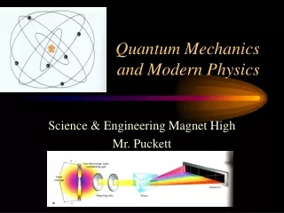
Quantum wells en modern electronics
460 likes | 670 Vues
Quantum wells en modern electronics. Annalisa Fasolino Theoretische Fysica, Nijmegen. Here you find the slides of the talk given October 24th in Nijmegen. If you wish you can find more information and addresses of many useful internet sites in the slides of my lectures for the course

Quantum wells en modern electronics
E N D
Presentation Transcript
Quantum wellsenmodern electronics Annalisa Fasolino Theoretische Fysica, Nijmegen Here you find the slides of the talk given October 24th in Nijmegen. If you wish you can find more information and addresses of many useful internet sites in the slides of my lectures for the course “Natuurkunde in de praktijk: nanotechnologie” at http://www.sci.kun.nl/tvs/people/fasolino.html/teaching.shtml
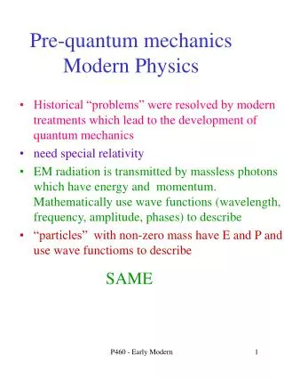
Quantum wellsenmodern electronics • which are the effects needed • basic function of device elements • electrons in solids are the players in the game • how can we use their quantum mechanical nature to achieve new effects • the need for new artificial materials • a success story till now but new ideas are needed if we want to keep the pace we have witnessed in the last ten years Annalisa Fasolino, Theoretische Fysica, Nijmegen
Wishes for devices • fast electronics: high frequency GHz • mobile telephones, satellite receivers (TV), computers • optoelectronics : current light • lasers, LED, telecommunications (light through fibres) • solar cells, photocells, light detectors • as small as possible • as fast as possible • low operating costs, small consumption • cheap Which applications
Basic function • Switch current on/off • amplification of signals • small action, big effect r varied by external bias = device Vout Vmod~100mV With it you can -Switch on/off - Amplify Vmod to Vout r R Vout= Vext r/(r+R) Vext= 9V
Variable resistance L=length A=surface n=number of charge carriers e=electron charge =time between collisions m=mass in practice n is the only parameter which can be changed but in metals n is fixed (~1 electron per atom), in semiconductors it can be changed by doping
Crystals Regular periodic arrangement of atoms in a lattice Simple cubic Face centered cubic fcc From http://www.lassp.cornell.edu/sethna/Tweed/Cubic_Crystals.html fcc unit cell From http://www.jwave.vt.edu/crcd/farkas/lectures/structure/tsld001.htm
a 0.1 nm L cm Effects of periodicity (formal) Wavefunction must be the same at symmetric positions Periodic with period a Plane wave This condition is satisfied only for some values of energy
Effects of periodicity (intuitive) Waves do not scatter (as particles do) if the order is perfect mean free path in metals can be cm, electrons behave almost as if the periodic potential did not exist Constructive interference for some wavelengths,destructive for others
empty filled empty empty filled filled Metals, semiconductors and insulators Energy of electrons Fermi energy metal semiconductor insulator
GaAs band structure Conduction band (empty) gap Eg Valence band (full)
Metals Insulators Cu 4s1 C 2s22p2 electrons loosely bound to nuclei , “electron gas” electrons form strong covalent bonds energy gap between occupied and empty states NO YES
Periodic table around semiconductors Valence electrons
Doping The most important property of semiconductors is represented by the possibility of doping with atoms with one electron more or one electron less than what is needed for covalent bonds Typical concentrations 1 atom every 100 million
Doped + Interaction with extra proton empty doped filled filled filled good and bad of doping One electron too much (too little). Extra electron does not participate to bonding but remains nearly free +allows to control amount of free carriers, low density - ionized impurities cause scattering, reduce mobility
Effect of external voltage (bias) Equilibrium: Coulomb force from ions prevents migration across junction Reverse bias: applied electric field further prevents flow across junction Forward bias: applied electric field assists electrons in overcoming the Coulomb barrier of the space charge in depletion region
I-V characteristic Diodes used for rectification, AM-FM detector, ...
Metal Oxide Semiconductor Field Effect Transistor (MOSFET) 1 cm First metal-insulator-semiconductor Field Effect Transistor (~1960) Present day dimensions 0.4 m (2000 lattice parameters) wide 10 nm (50 lattice parameters) thick active layer
V=0 V>Vth Metal Oxide Field Effect Transistor (MOS) V between metal gate and p-substrate creates n-conducting channel -> source-drain resistance decreases dramatically Almost no current passes (vertically) through oxide But many impurities in conducting channel (dissipation, ‘slow’)
SiO2 SiO2 p-Si p-Si 10nm 10nm CB-edge E=eFx CB-edge E=eFx Near the SiO2-Si interface Classical Quantum Mechanical E1 E2 But such short and steep variations of the potential require a Q.M. description. H=(p2/2m + eFx) =E Electron density Electron density = * maximal minimal distance distance
- - - - - - - - - - - - - - Conducting channel doped layer undoped sc 1 undoped sc 2 with smaller gap Getting rid of impurities: selective doping Unstable: charge transfer ---> band bending Heterostructures: Two layers of different semiconductors with different bandgaps. Separate electrons from ionized impurities !
Molecular Beam Epitaxy (MBE) Mechanism for RHEED specular spot oscillations during growth Typical MBE growth chamber
Mobility High -> high speed
optical transitions Absorption or emission of photons between full and empty states Needs photon energy equal to the energy separation of electronic levels absorption emission 6.63 10-34 Js 3 10 8 m/s E(eV) 1.6 10-19 J/eV E=1eV -> =1.243 m
Some frequencies are more useful than others Transmission of light in air: best between 3 and 4 m
Attenuation in optical fibers Glass fibers for telecommunication, best between 1.3-1.55 m Attenuation less than 0.1 db/km
E Quantum well (QW) width L, infinite barriers 2D: electrons are bound along x, free to move perpendicularly parabolic dependence
Ga Al As a QW ! The principle of a semiconductor QW New artificial material formed by thin layers of semiconductors with different energy gaps AlAs GaAs AlAs Bound states electron Bound states holes new, larger gap
Absorption from 3D to 2D 400 nm 21 nm 14 nm 10 meV well width linewidth 1 19.8 nm 0.25 meV 2 12.2 nm 0.4 meV 3 8.3 nm 1.0 meV 4 5.1 nm ~ 5 meV F. Pulizzi et al., Magnet Lab Nijmegen, 2001 From R. Dingle Festkoerperprobleme 15,21 (1975)
The philisophy of semiconductor technology, a success story • Let’s make existing material smaller and smaller • If the material we need does not exist let’s make it ourselves • use quantum confinement to tune electronic and optical properties • new things happen on the nanometer scale • look for new fundamental physics AND for applications/devices Present technology based on miniaturization and layer by layer growth
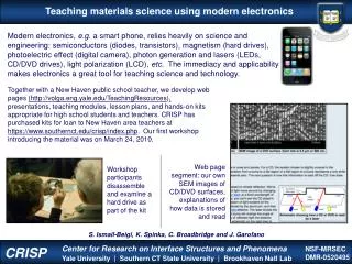
So successful that also Britney Spears knows a lot about semiconductors
And now? • Present technology based on scaling down from `big` to small, is reaching its limits. • Limits of lithography, structures and contacts • Dissipation • Interconnects • Effect of interfaces
Quantum wires and quantum dots QW are by now used in many commercial devices. Why not try and confine electrons also in the other one or two directions? Quantum wires: etch selectively with chemicals to create 1D structures. Confinement effects need wires about 10 nm wide (1000 thinner than a hair). It turns out that it is very difficult (and expensive) to create 1D (wires) and 0D (dots) structures on nm scale by chemical etching
Let’s nature help: look for self-organization Growth on non-planar grooved structures From http://imowww.epfl.ch/Nanoweb/default.htm Thicker GaAs (the wire) at the bottom of the groove results from the competition between the growth rate anisotropy on the different facets of the groove and the surface diffusion of adatoms.
Wavefunction in quantum wires From http://www.ifm.liu.se/Matephys/ AAnew/research/iii_v/qwr.htm#S1.2
Turn a failure into a success When the lattice mismatch is too big, layers turn into dots
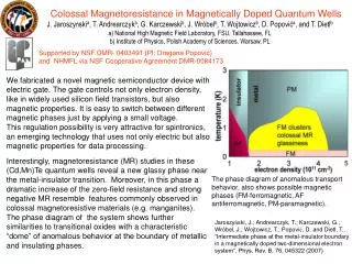
Self-organized InAs quantum dots From http://www.ifm.liu.se/Matephys/AAnew/research/iii_v/qwr.htm#S1.2 The dots are formed during spontaneous reorganisation of a sequence of AlGaAs and strained InGaAs epitaxial films grown on GaAs (311)B substrates. The size of the quantum dots are as small as 20 nm
Future • Semiconductor technology based of sophisticated techniques and concepts has been very successful but is reaching its limits. • New technology based on ‘bottom up’ is being developed but far from maturity • Molecular electronics (switching one molecule) • Self-organisation of molecules, clusters, carbon nanotubes. • As Feynman said ‘there is plenty of room at the bottom’ but: • Almost everything needs to developed from scratch again.