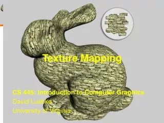
Texture Mapping
Texture Mapping. Why texture map? How to do it How to do it right Spilling the beans A couple tricks Difficulties with texture mapping Projective mapping Shadow mapping Environment mapping. The Quest for Visual Realism.

Texture Mapping
E N D
Presentation Transcript
Texture Mapping • Why texture map? • How to do it • How to do it right • Spilling the beans • A couple tricks • Difficulties with texture mapping • Projective mapping • Shadow mapping • Environment mapping Slide 1
The Quest for Visual Realism • For more info on the computer artwork of Jeremy Birnsee http://www.3drender.com/jbirn/productions.html Slide 2
Photo-textures The concept is very simple! Slide 3
(0,1) (0,0) (1,0) Texture Coordinates public void Draw(Raster raster) { : PlaneEqn(uPlane, u0, u1, u2); //scaled by width PlaneEqn(vPlane, v0, v1, v2); //scaled by height : for (y = yMin; y <= yMax; y += raster.width) { e0 = t0; e1 = t1; e2 = t2; u = tu; v = tv; z = tz; boolean beenInside = false; for (x = xMin; x <= xMax; x++) { if ((e0 >= 0) && (e1 >= 0) && (e2 >= 0)) { int iz = (int) z; if (iz <= raster.zbuff[y+x]) { int uval = tile(u, texture.width); int vval = tile(v, texture.height); int pix = texture.getPixel(uval, vval); if ((pix & 0xff000000) != 0) { raster.pixel[y+x] = pix; raster.zbuff[y+x] = iz; } } beenInside = true; } else if (beenInside) break; e0 += A0; e1 += A1; e2 += A2; z += Az; u += Au; v += Av; } t0 += B0; t1 += B1; t2 += B2; tz += Bz; tu += Bu; tv += Bv; } } • Specify a texture coordinate at each vertex (s, t) or (u, v) • Canonical coordinates where u and v are between 0 and 1 • Simple modifications to triangle rasterizer Slide 4
The Result Let's try that out ... Texture mapping applet (image) Wait a minute... that doesn't look right. What's going on here? Let's try again with a simpler texture... Texture mapping applet (simple texture) Notice how the texture seems to bend and warp along the diagonal triangle edges. Let's take a closer look at what is going on. Slide 5
Looking at One Edge First, let's consider one edge from a given triangle. This edge and its projection onto our viewport lie in a single common plane. For the moment, let's look only at that plane, which is illustrated below: Slide 6
Visualizing the Problem Notice that uniform steps on the image plane do not correspond to uniform steps along the edge. WLOG, let's assume that the viewport is located 1 unit away from the center of projection. Slide 7
Linear Interpolation in Screen Space Compare linear interpolation in screen space Slide 8
Linear Interpolation in 3-Space to interpolation in 3-space Slide 9
How to Make Them Mesh Still need to scan convert in screen space... so we need a mapping from t values to s values. We know that the all points on the 3-space edge project onto our screen-space line. Thus we can set up the following equality: and solve for s in terms of t giving: Unfortunately, at this point in the pipeline (after projection) we no longer have z1 lingering around (Why?). However, we do have w1= 1/z1 and w2 = 1/z2 . Slide 10
Interpolating Parameters We can now use this expression for s to interpolate arbitrary parameters, such as texture indices (u, v), over our 3-space triangle. This is accomplished by substituting our solution for s given t into the parameter interpolation. Therefore, if we premultiply all parametersthat we wish to interpolate in 3-space by their corresponding w value and add a new plane equation to interpolate the w values themselves, we can interpolate the numerators and denominator in screen-space. We then need to perform a divide a each step to get to map the screen-space interpolants to their corresponding 3-space values. Once more, this is a simple modification to our existing triangle rasterizer. Slide 11
Modified Triangle Code PlaneEqn(uPlane, (u0*w0), (u1*w1), (u2*w2)); PlaneEqn(vPlane, (v0*w0), (v1*w1), (v2*w2)); PlaneEqn(wPlane, w0, w1, w2); for (y = yMin; y <= yMax; y += raster.width) { e0 = t0; e1 = t1; e2 = t2; u = tu; v = tv; w = tw; z = tz; boolean beenInside = false; for (x = xMin; x <= xMax; x++) { if ((e0 >= 0) && (e1 >= 0) && (e2 >= 0))) { int iz = (int) z; if (iz <= raster.zbuff[y+x]) { float denom = 1.0f / w; int uval = (int) (u * denom + 0.5f); uval = tile(uval, texture.width); int vval = (int) (v * denom + 0.5f); vval = tile(vval, texture.height); int pix = texture.getPixel(uval, vval); if ((pix & 0xff000000) != 0) { raster.pixel[y+x] = pix; raster.zbuff[y+x] = iz; } } beenInside = true; } else if (beenInside) break; e0 += A0; e1 += A1; e2 += A2; z += Az; u += Au; v += Av; w += Aw; } t0 += B0; t1 += B1; t2 += B2; tz += Bz; tu += Bu; tv += Bv; tw += Bw; Slide 12
Demonstration For obvious reasons this method of interpolation is called perspective-correct interpolation. The fact is, the name could be shortened to simply correct interpolation. You should be aware that not all 3-D graphics APIs implement perspective-correct interpolation. Applet with correct interpolation You can reduce the perceived artifacts of non-perspective correct interpolation by subdividing the texture-mapped triangles into smaller triangles (why does this work?). But, fundamentally the screen-space interpolation of projected parameters is inherently flawed. Applet with subdivided triangles Slide 13
When we did Gouraud shading didn't we interpolate illumination values, that we found at each vertex using screen-space interpolation? Didn't I just say that screen-space interpolation is wrong (I believe "inherently flawed" were my exact words)? Does that mean that Gouraud shading is wrong? Is everything that I've been telling you all one big lie? Has 6.837 amounted to a total waste of time? Slide 14
Yes, Yes, Yes, Maybe, and No, you've been exposed to nice purple cows. Gourand shading is wrong. However, you usually will not notice because the transition in colors is very smooth (And we don't know what the right color should be anyway, all we care about is a pretty picture). • There are some cases where the errors in Gouraud shading • become obvious. • When switching between different levels-of-detail representations • At "T" joints. Applet showing errors in Gouraud shading Slide 15
Texture Tiling Often it is useful to repeat or tile a texture over the surface of a polygon. This was implemented in the tile method of the examples that I gave. … float denom = 1.0f / w; int uval = (int) (u * denom + 0.5f); uval = tile(uval, texture.width); int vval = (int) (v * denom + 0.5f); vval = tile(vval, texture.height); … private int tile(int val, int size) { if (val >= size) { do { val -= size; } while (val >= size); } else { while (val < 0) { val += size; } } return val; } Tiling applet Slide 16
Texture Transparency There was also a little code snippet to handle texture transparency. … int pix = texture.getPixel(uval, vval); if ((pix & 0xff000000) != 0) { raster.pixel[y+x] = pix; raster.zbuff[y+x] = iz; } … Applet showing texture transparency Now you can all go out and write DOOM! (or better still play Doom!) Slide 17
Purple Cow Doom • eye 0 0 6 • look 0 1 6 • up 0 0 1 • fov 60 • la 1 1 1 • ld 1 1 1 0.5 0.5 -1 • surf 0.8 0.2 0.9 0.5 0.5 0.0 1.0 • texture carpet.gif • v -30 -30 0 • v 30 -30 0 • v 30 30 0 • v -30 30 0 • tf 0 0 0 1 10 0 2 10 10 3 0 10 • texture ceilingtile.gif • v -30 -30 10 • v 30 -30 10 • v 30 30 10 • v -30 30 10 • tf 7 0 0 6 15 0 5 15 15 4 0 15 texture walls.gif v -20 20 0 v 20 20 0 v 20 20 10 v -20 20 10 tf 8 0 0.25 9 1 0.25 10 1 0 11 0 0 v 15 -20 0 v 15 20 0 v 15 20 10 v 15 -20 10 tf 12 1 0.5 13 0 0.5 14 0 0.25 15 1 0.25 v 5 10 0 v 10 10 0 v 5 15 0 v 10 15 0 v 5 10 10 v 10 10 10 v 5 15 10 v 10 15 10 tf 16 0.9 0.25 17 1 0.25 21 1 0 20 0.9 0 tf 16 0.9 0.25 18 1 0.25 22 1 0 20 0.9 0 tf 17 0.9 0.25 19 1 0.25 23 1 0 21 0.9 0 tf 18 0.9 0.25 19 1 0.25 23 1 0 22 0.9 0 Slide 18
Summary of Label Textures • Increases the apparent complexity of simple geometry • Must specify texture coordinates for each vertex • Projective correction (can't linearly interpolate in screen space) • Specify variations in shading within a primitive • Two aspects of shading • Illumination • Surface Reflectace • Label textures can handle both kinds of shading effects but it gets tedious • Acquiring label textures is surprisingly tough Slide 19
Difficulties with Label Textures • Tedious to specfiy texture coordinates for every triangle • Textures are attached to the geometry • Easier to model variations in reflectance than illumination • Can't use just any image as a label texture • The "texture" can't have projective distortions • Reminder: linear interploation in image space is not equivalent to linear interpolation in 3-space (This is why we need "perspective-correct" texturing). The converse is also true. • Textures are attached to the geometry • Easier to model variations in reflectance than illumination • Makes it hard to use pictures as textures Slide 20
Projective Textures • Treat the texture as a light source (like a slide projector) • No need to specify texture coordinates explicitly • A good model for shading variations due to illumination • A fair model for reflectance (can use pictures) Slide 21
Projector Geometry (See last lecture for details on how to compute thePmatrix) Slide 22
The Mapping Process • During the Illumination process: • For each vertex of triangle(in world or lightingspace) • Compute ray from the projective texture's origin to point • Compute homogeneous texture coordinate, [ti, tj, t](use equation from last slide) • During scan conversion(in projected screen space) • Interpolate all three texture coordinates in 3-space • (premultiply byw of vertex) • Do normalization at each rendered pixeli = t i /tj = t j / t • Access projected texture Slide 23
Projective Texture Mapping as a Light Source public Light(float px, float py, float pz, float lx, float ly, float lz, float upx, float upy, float upz, float hfov, Raster r) { lightType = SHADER; float t, ux, uy, uz, vx, vy, vz; x = px; y = py; z = pz; ir = 0; ig = 0; ib = 0; lx = lx - x; ly = ly - y; lz = lz - z; t = (float)(1 / Math.sqrt(lx*lx + ly*ly + lz*lz)); lx *= t; ly *= t; lz *= t; ux = ly*upz - lz*upy; uy = lz*upx - lx*upz; uz = lx*upy - ly*upx; t = (float)(1 / Math.sqrt(ux*ux + uy*uy + uz*uz)); ux *= t; uy *= t; uz *= t; vx = ly*uz - lz*uy; vy = lz*ux - lx*uz; vz = lx*uy - ly*ux; t = (float)(1 / Math.sqrt(vx*vx + vy*vy + vz*vz)); vx *= t; vy *= t; vz *= t; t = (float)(1 / (2*Math.tan((0.5*hfov)*Math.PI/180))); lx = lx*t - 0.5f*(ux + vx); ly = ly*t - 0.5f*(uy + vy); lz = lz*t - 0.5f*(uz + vz); setProjective(lx, ly, lz, ux, uy, uz, vx, vy, vz); // Inverts matrix lightTexture = r; } Slide 24
A Little More Code In Triangle.Illuminate( ) ... lx = vlist[v[j]].x - l[i].x; ly = vlist[v[j]].y - l[i].y; lz = vlist[v[j]].z - l[i].z; float u, v, w; u = l[i].m[0]*lx + l[i].m[1]*ly + l[i].m[2]*lz; v = l[i].m[3]*lx + l[i].m[4]*ly + l[i].m[5]*lz; w = l[i].m[6]*lx + l[i].m[7]*ly + l[i].m[8]*lz; tq[j] = (int) (lightTexture.width*TSCALE*u); ts[j] = (int) (lightTexture.height*TSCALE*v); tt[j] = (int) (TSCALE*w); In Triangle.ScanConvert( ) after setting up plane equations for q, s, and t... int i = (int) (q/t); int j = (int) (s/t); if (i < 0) i = 0; else if (i >= lightTexture.width) i = lightTexture.width - 1; if (j < 0) j = 0; else if (j >= lightTexture.height) j = lightTexture.height - 1; int rgb = lightTexture.getPixel(i, j); Slide 25
The texture used was Since we are viewing the scene from a slightly different point of view than the projective texture we see some points that are not shaded. These are the two textures that were used: and . Projective Texture Examples First, let's consider projective textures as a source of illumination... Projective Texture Applet (Teapot) First, let's consider projective textures to model reflectance... Projective Texture Applet (Cow) Slide 26
Shadow Maps Textures can also be used to generate shadows. First, the scene is rendered from the point of view of each light source, but only the depth-buffer values are retained. In this example the closer points are lighter and more distant parts are darker (with the exception of the most distant value which is shown as white for contrast) As each pixel is shaded (once more shadow mapping assumes that the illumination model is applied at each pixel) a vector from the visible point to the light source is computed (Remember it is needed to compute, N•L). As part of normalizing it we compute its length. If we find the projection of the 3D point that we are shading onto each lights shadow buffer we can compare this length with the value stored in the shadow buffer. If the shadow-buffer is less than the current point's length then the point is in shadow and the corresponding light source can be ignored for that point. Projective Textures with Depth Slide 27
Environment Maps If, instead of using the ray from the surface point to the projected texture's center, we used the direction of the reflected ray to index a texture map. We can simulate reflections. This approach is not completely accurate. It assumes that all reflected rays begin from the same point, and that all objects in the scene are the same distance from that point. Slide 28
What's the Best Chart? Slide 29
Other Texture Mappings A small variation on environment maps - specular maps. Specular maps can model extended or area light sources in the scene. This can be done in combination with modeling the environment. This approach gives a much smoother highlight when per-vertex shading is used to compute specular highlights. Slide 30
Reflection Mapping Slide 31
Next Time: More Texture Mapping but for now, let's play Purple Cow Doom some more… Slide 33