Inside CDF Operations
Inside CDF Operations. Steve Hahn Fermilab May 23, 2005. Outline. General comments about CDF Operations and Monitoring and Control Systems (MCS) General comments about CDF detector alignment and beamlines. Who am I?.

Inside CDF Operations
E N D
Presentation Transcript
Inside CDF Operations Steve Hahn Fermilab May 23, 2005
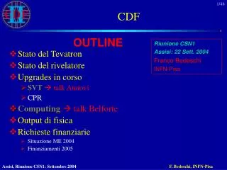
Outline • General comments about CDF Operations and Monitoring and Control Systems (MCS) • General comments about CDF detector alignment and beamlines
Who am I? • Started on CDF in 1984 as U. of Pennsylvania post-doc constructing, testing, and calibrating central calorimeter wedges, specifically radioactive sources and electron and pion beams for calibration • Joined FNAL in CDF Operations group 1988 • Operations manager “emeritus”—active daily in operations and shift crew training • Subproject leader (SPL) of MCS group • Not a tracking or beamlines expert, but do have some operational experience
CDF MCS Nomenclature • Synonymous (but incorrectly so) in CDF: • Monitoring and Control Systems (MCS) for CDF Run II • “Slow Controls”: those CDF devices which do not have to be read out at data-taking rates (L1 rate 2.52 MHz); instead, 60 Hz to minutes • iFIX: actual Windows program suite which provides interface to MCS for display and control of devices (more properly, Intellution owned by GE FANUC) • APACS: crate system with high degree of redundancy using PLCs, and rated for life safety (however, most user systems are not read out via APACS)
MCS Images Cryo Room (6 process system PCs under table and more in back room) APACS chassis containing two racks—each card has PLC; racks have redundant power supplies and busses Typical iFIX “picture” (collision hall HVAC) with fans, valves, temp readouts, and controls Main iFIX “picture” with links to others
iFIX (Intellution) • Large suite of related programs for networked: • SCADA (software control and data acquisition) nodes • View (display only, no control) nodes • We have about 35 nodes falling into several categories: • Server nodes: centralized network mounted disk (with local fallback if network lost) and webserver • “Process system” nodes in CDF cryo room: control life safety and other infrastructure systems via APACS (30 Hz, 60 Hz) interfaced to PC via Siemens M-BUS card • Flammable gas, oxygen deficiency hazard • Solenoid cryogenics • Building and collision hall HVAC • VME rack safety and chilled water • APACS channels (“points”) expensive: $1000s for one card with 10-30 channels
iFIX (Intellution) • Detector nodes reading out channels via interface cards—SCSI CAMAC, CAENet, RS-422—in PC (from 60 Hz to minutes); much less expensive • Detector HVs and currents, LVs and currents, bias voltages and currents, and more stored in local iFIX database on that node • Typically one node per detector: central, plug, muon chambers, muon scintillators, TOF scintillators, COT, VME power supplies, calorimeter and PMT temperatures • Silicon (SVX, ISL, L00) cooling and interlocks especially complicated • Chilled water (negative pressure) compensates for varying heat load depending on state of electronics, HV, and bias voltages • Try to avoid thermal cycles: both makes S/N worse and possible damage to silicon bulkheads • Also have to worry about dewpoints resulting in condensation on chilled water lines inside detector • Use Siemens rack for chilled water and interlocks and VME readout cards for HV from CAEN 527s
iFIX (Intellution) • Two special nodes in control room–VNODE1 and VNODE2 • Allow global control and display of CDF by monitoring ace; talks to all other nodes (thus, need for heartbeats to ensure other node is not dead) • Global Alarms • HV Summary
iFIX (Intellution) • iFIX provides: • CASE tools to develop “pictures” with automatically generated code in either Visual C++ or Basic • Other tools to: • Connect common interface type channels to local iFIX databases; “process system” nodes need little additional coding (but see below about 4mation) • Provide security via user logins (each iFIX user has certain privileges) and alarm zones (each device only can be viewed/controlled on certain nodes and with certain logins) • Setup system startup and shutdown; for example: • Startup starts all desired programs and iFIX “pictures” • Most nodes cannot be shutdown without privileged iFIX login • Does not usually work with user interfaces; additional code needs to be written in either Visual C++ or Basic using Visual Studio for building and linking • APACS 4mation provides: • CASE tools to develop logic in APACS PLCs to control process systems • These tools are in system engineer terms—logic blocks and feedback blocks • We have several engineers from FESS (Fermilab Engineering Services and Support) who work on this part-time for us and part-time for other experiments
iFIX Problems • Historically, one institution has worked on one detector node; as time passes, expertise dwindles • Since most institutions built original systems on their own, they often included other packages—LabView, LabWindows, MS Foundation Classes—for the user interface instead of iFIX “pictures”. This meant system could only be controlled completely from detector node itself. • Many layers to support with large overhead each time: • Windows: NT 2000 XP along with newer more powerful PCs (XP now mandated for computer security) • Visual C++ or Basic and Visual Studio: 5.0 6.0 .NET • iFIX: 2.2 3.0 need to do • Computer security: • Once had usual virus/spyware problems with Windows; now each incident is under scrutiny • Run isolated subnet with router/firewall • Virus checking and definition download and backup software all can be potential sources of slowdowns/freezes • Life safety: • Must work even during power outage • Use UPS’s backed up by diesel generator which starts automatically when power outage detected
Getting MCS data into DAQ stream • Special client (ICICLE) runs on iFIX node: • Polls local iFIX databases for channels requested by detector groups • Records all data outside window (from defined mean and tolerance) every 10 minutes • Records all data once every hour • Communicates with runControl (DAQ program) via SmartSockets (proprietary messaging protocol for various OS including Windows and Vxworks on our VME processors) • DAQ complains if it finds ICICLE not running while data-taking • For most but not all data, data collection only occurs while a physics run is in progress • Inserts data into our online production ORACLE database (CDFONPRD) indexed by time • Various tools to look at data numerically or graphically • Selected data is passed from online DB to offline DB for use in analysis • Some groups use other methods to store data at higher rate: • Store data additionally in MS Access DB and backup to CD or DVD • iFIX can take any channel and make “historical plots”; data is only archived if channel is defined in historical plot. This data is also backed up to DVDs.
From scratch:what would I do different? • Look for *NIX-based solution • All our DAQ machines are LINUX-based. Why support two different OSes? Especially Windows with its security problems. • However, may not be possible; depends on interface drivers. Many interfaces now going to OPC specifications which provides one broad interoperable definition for interfaces, clients, and servers; but often only work on Windows (based on MS DCOM) • Know CMS is going to PVSS (similar to iFIX but for both LINUX and Windows), but for just the above reasons, using Windows, not LINUX • But overhead may be so costly, may be worthwhile to customize to interfaces usable with LINUX • Avoid custom solutions • Just more packages to maintain over life of experiment • May break features of your main automation software • Broader support of detector systems • Pool of support coding experts? • Code written with some minimum criteria to allow others to get up to speed quickly?
2nd subject:Detector alignment and beamlines • CDF’s case: • Detector and beampipe alignment originally determined by survey (using laser transits onto survey targets) • SVX relative to COT determined by Rasnik system (cameras viewing fixed grids); motion via SVX inchworms (problematic, not used) • Weight of central detector and yoke cause gradual sinking of detector, necessitating repeated surveys and moves of all pieces: • Central detector raised and lowered via pneumatic jacks • SVX lowered (but not raised) via inchworms • Beampipe moved as needed • Commissioning quickly brought up XFT (fast tracker/trigger through COT) and SVT (displaced vertex tracker/trigger using silicon) • First provides primary vertex detection • Second provides realtime detection of beamline (means and sigmas at z=0 and slopes) through the detector; these are feed from our detector back into accelerator ACnet system for immediate feedback for beam tuning • Tevatron was in worse shape at start of Run II then ever before; only after two summer shutdowns were sufficient Tevatron magnet moves and rolls done to smooth out beam orbits (most noticeable difference being beam losses are down 10X) • Still, beam tuning must also be taken into account on top of all other effects
Detector alignment and beamlines • Also, beamlines are calculated both online in data monitoring, and offline for precise tracking calibration • One last item: cradles containing low beta quadrapole trains (6 quads on each side of central detector running from embedded in forward muon walls back into Tevatron enclosures) • Were suspended from Invar rods dropped from I-beams on ceiling of collision hall, but I-beams were only tied at east and west walls of collision hall; also Invar rods from side walls of collision hall to prevent horizontal motion • Entire system was susceptible to oscillations induced by air from HVAC blowing over rods and perhaps temperature effects • Last “summer” shutdown removed Invar bars and instead supported cradles from below via steel columns with motion sensors referenced to central detector location • Also contributed to much more stable beamline and beam losses
Detector alignment and beamlines Low beta quad cradle movement @ A4 (p side horz and vert) and B1 (pbar side horz and vert); Invar bars have not been disconnected on pbar side–will need longer access to do this; also, want to see before vs. after on beam movement Vertical scale - 10 or 20 µ/div Horizontal scale - one week from Nov. 25 to Dec. 2 Invar rods Sheilding surrounding but not supporting crade Column
Detector alignment and beamlines Recent SVT positions and slopes (only sensible during physics data-taking) Recent low- quad positions
Detector alignment and beamlines From run 138428 on 02/04/2002 to run 198152 on 05/17/2005 Summer Shutdown 2003 Summer Shutdown 2004