Download
1 / 25
250 likes | 278 Vues
Learn about torsion theory, torsional shearing stress, angle of twist, and power transmission in shafts through solved problems. Understand shear and moment in beams in static determinate and indeterminate structures.

E N D
Strength of Material-5 Torsion Dr. Attaullah Shah
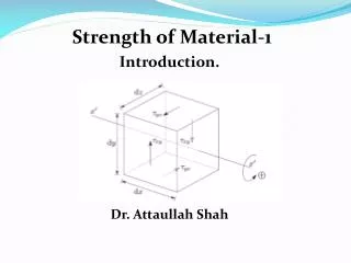
Consider a bar to be rigidly attached at one end and twisted at the other end by a torque or twisting moment T equivalent to F × d, which is applied perpendicular to the axis of the bar, as shown in the figure. Such a bar is said to be in torsion. TORSIONAL SHEARING STRESS, For a solid or hollow circular shaft subject to a twisting moment T, the torsional shearing stress at a distance ρ from the center of the shaft is where J is the polar moment of inertia of the section and r is the outer radius.
ANGLE OF TWIST The angle θ through which the bar length L will twist is where T is the torque in N·mm, L is the length of shaft in mm, G is shear modulus in MPa, J is the polar moment of inertia in mm4, D and d are diameter in mm, and r is the radius in mm. POWER TRANSMITTED BY THE SHAFT A shaft rotating with a constant angular velocity ω (in radians per second) is being acted by a twisting moment T. The power transmitted by the shaft is where T is the torque in N·m, f is the number of revolutions per second, and P is the power in watts.
Solved Problems • 304 A steel shaft 3 ft long that has a diameter of 4 in. is subjected to a torque of 15 kip·ft. Determine the maximum shearing stress and the angle of twist. Use G = 12 × 106 psi.
Problem 305 What is the minimum diameter of a solid steel shaft that will not twist through more than 3° in a 6-m length when subjected to a torque of 12 kN·m? What maximum shearing stress is developed? Use G = 83 GPa.
Problem 306 A steel marine propeller shaft 14 in. in diameter and 18 ft long is used to transmit 5000 hp at 189 rpm. If G = 12 × 106 psi, determine the maximum shearing stress.
Problem 308 A 2-in-diameter steel shaft rotates at 240 rpm. If the shearing stress is limited to 12 ksi, determine the maximum horsepower that can be transmitted.
Problem 309 A steel propeller shaft is to transmit 4.5 MW at 3 Hz without exceeding a shearing stress of 50 MPa or twisting through more than 1° in a length of 26 diameters. Compute the proper diameter if G = 83 GPa.
Problem 310 Show that the hollow circular shaft whose inner diameter is half the outer diameter has a torsional strength equal to 15/16 of that of a solid shaft of the same outside diameter.
Problem 316 A compound shaft consisting of a steel segment and an aluminum segment is acted upon by two torques as shown in Fig. P-316. Determine the maximum permissible value of T subject to the following conditions: τst = 83 MPa, τal = 55 MPa, and the angle of rotation of the free end is limited to 6°. For steel, G = 83 GPa and for aluminum, G = 28 GPa.
Problem 311 An aluminum shaft with a constant diameter of 50 mm is loaded by torques applied to gears attached to it as shown in Fig. P-311. Using G = 28 GPa, determine the relative angle of twist of gear D relative to gear A.
Problem 316 A compound shaft consisting of a steel segment and an aluminum segment is acted upon by two torques as shown in Fig. P-316. Determine the maximum permissible value of T subject to the following conditions: τst = 83 MPa, τal = 55 MPa, and the angle of rotation of the free end is limited to 6°. For steel, G = 83 GPa and for aluminum, G = 28 GPa
Problem 317 A hollow bronze shaft of 3 in. outer diameter and 2 in. inner diameter is slipped over a solid steel shaft 2 in. in diameter and of the same length as the hollow shaft. The two shafts are then fastened rigidly together at their ends. For bronze, G = 6 × 10⁶ psi, and for steel, G = 12 × 106 psi. What torque can be applied to the composite shaft without exceeding a shearing stress of 8000 psi in the bronze or 12 ksi in the steel? • Solve yourself.
Shear & Moment in Beams • DEFINITION OF A BEAM • A beam is a bar subject to forces or couples that lie in a plane containing the longitudinal of the bar. According to determinacy, a beam may be determinate or indeterminate. • STATICALLY DETERMINATE BEAMS • Statically determinate beams are those beams in which the reactions of the supports may be determined by the use of the equations of static equilibrium. The beams shown below are examples of statically determinate beams.
STATICALLY INDETERMINATE BEAMS • If the number of reactions exerted upon a beam exceeds the number of equations in static equilibrium, the beam is said to be statically indeterminate. In order to solve the reactions of the beam, the static equations must be supplemented by equations based upon the elastic deformations of the beam. • The degree of indeterminacy is taken as the difference between the umber of reactions to the number of equations in static equilibrium that can be applied. In the case of the propped beam shown, there are three reactions R1, R2, and M and only two equations (ΣM = 0 and sum;Fv = 0) can be applied, thus the beam is indeterminate to the first degree (3 – 2 = 1).
TYPES OF LOADING • Loads applied to the beam may consist of a concentrated load (load applied at a point), uniform load, uniformly varying load, or an applied couple or moment. These loads are shown in the following figures.
Relationship between Load, Shear, and Moment The vertical shear at C in the figure shown in previous section is taken as where R1 = R2 = wL/2 If we differentiate M with respect to x: Thus, the rate of change of the bending moment with respect to x is equal to the shearing force, or the slope of the moment diagram at the given point is the shear at that point. Thus Thus, the rate of change of the bending moment with respect to x is equal to the shearing force, or the slope of the moment diagram at the given point is the shear at that point. Differentiate V with respect to x gives Thus, the rate of change of the shearing force with respect to x is equal to the load or the slope of the shear diagram at a given point equals the load at that point.
PROPERTIES OF SHEAR AND MOMENT DIAGRAMS • The following are some important properties of shear and moment diagrams: • The area of the shear diagram to the left or to the right of the section is equal to the moment at that section. • The slope of the moment diagram at a given point is the shear at that point. • The slope of the shear diagram at a given point equals the load at that point. • The maximum moment occurs at the point of zero shears. This is in reference to property number 2, that when the shear (also the slope of the moment diagram) is zero, the tangent drawn to the moment diagram is horizontal. • When the shear diagram is increasing, the moment diagram is concave upward. • When the shear diagram is decreasing, the moment diagram is concave downward.
SIGN CONVENTIONS • The customary sign conventions for shearing force and bending moment are represented by the figures below. • A force that tends to bend the beam downward is said to produce a positive bending moment. A force that tends to shear the left portion of the beam upward with respect to the right portion is said to produce a positive shearing force. • An easier way of determining the sign of the bending moment at any section is that upward forces always cause positive bending moments regardless of whether they act to the left or to the right of the exploratory section.
Problem 426 Cantilever beam acted upon by a uniformly distributed load and a couple as shown in Fig. P-426.
Problem 446 Beam loaded and supported as shown in Fig. P-446.
Assignment • Problem 273 The composite bar shown in Fig. P-273 is firmly attached to unyielding supports. An axial force P = 50 kips is applied at 60°F. Compute the stress in each material at 120°F. Assume α = 6.5 × 10⁻⁶ in/(in·°F) for steel and 12.8 × 10⁻⁶ in/(in·°F) for aluminum. • Problem 316 A compound shaft consisting of a steel segment and an aluminum segment is acted upon by two torques as shown in Fig. P-316. Determine the maximum permissible value of T subject to the following conditions: τst = 83 MPa, τal = 55 MPa, and the angle of rotation of the free end is limited to 6°. For steel, G = 83 GPa and for aluminum, G = 28 GPa. • Problem 417 For Beam carrying the triangular loading shown in Fig. P- 417 draw the shear force and bending moment diagrams.