Download
1 / 50
500 likes | 620 Vues
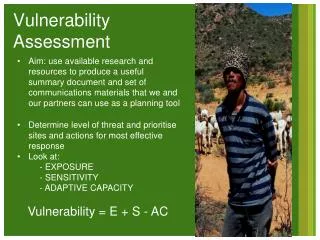
Vulnerability Assessment of Buildings Contribution from Large-scale Laboratory Tests. A. Pinto ELSA, JRC, Ispra (VA), Italy. Kocaeli (Turkey) Earthquake, August 17, 1999 (A. Elnashai, 1999). Mt. Parnes, Athens (Greece) Earthquake, Spet. 7, 1999 (M. Fardis & N. Bousias, 1999).

E N D
Vulnerability Assessment of Buildings Contribution from Large-scale Laboratory Tests A. Pinto ELSA, JRC, Ispra (VA), Italy
Kocaeli (Turkey) Earthquake, August 17, 1999 (A. Elnashai, 1999)
Mt. Parnes, Athens (Greece) Earthquake, Spet. 7, 1999 (M. Fardis & N. Bousias, 1999)
Reinforced Concrete Buildings • Represent the largest part of the European building stock at risk, in earthquake prone urban areas • Many of the important structures [Hospitals, Schools, Emergency management, …] are RC structures • There is a lack of codified guidelines for seismic Assessment and Re-design, in Europe • Design and Re-design may have different performance requirements
Seismic Assessment &Retrofit of RC buildings Why (causes)? Issues/Difficulties • Economical and political • High costs - compared with seismic resistance in new construction • Low premium market is willing to pay for higher safety • Tendency of politicians to avoid complex and socially sensitive problems • Design for earthquake resistance: No formal Seismic Design provisions- until the ‘50s in US and ‘60s in Europe • Provisions for design and detailing of members and structures: Standards in mid-’70s in US and mid-80s in Europe • Technical • Much easier to design a new ER buildings than to assess and strength an old one • Lack of codified criteria and rules for redesign, which leads to somehow arbitrary interventions …(existing for masonry buildings …) • Lack of control to the design, construction and maintenance processes
Assessment Determines the need for seismic retrofit or not Identifies particular weakness and deficiencies to be corrected Requires: Tools to allow rapid screening and empirical evaluation of existing structures ‘Solutions’: Conventional procedures Deformation and displacement based evaluation procedures(Performance and model calibration from Lab Tests required) Retrofitting To provide improved seismic performance Requirements: Technically feasible acceptable cost-benefit ratios (cost benefit analysis) Technical solutions according to the weakness identified in the assessment procedure (local and/or global) and to the protection required: Stiffness Strength Ductility (deformation capacity) Damping or isolation Assessment --- Retrofitting
Key ideas Seismic retrofitting combined with architectural remodeling, rehabilitation and/or change in use Find a feasible and acceptable solution allowing occupancy during the works Technical Requirements Any intervention should not prejudice the safety of any part of the building in any aspect Continuity of the load path(s) between new and existing elements, floors, … Foundations ?! Retrofitting solutions New Shear-walls Drift control, May solve irregularity problems, Design according to new codes, Foundations?! Steel Bracing (with/out dissipation devices) Very effective Connection between bracing and concrete very peculiar Jacketing (Steel, RC, FRC) Element strength and deformation capacity (local) Joints ?! Retrofitting ‘guidelines’ (General)
ICONS - Topic 2Assessment Strengthening & Repair ELSA TMR-Large-scale Facility European Laboratory for Structural Assessment (ELSA) EC, Joint Research Centre, ISIS, SSMU, TP480 2120 Ispra (VA), Italy
Assessment Strengthening & RepairThe research work is part of research programme of the ICONS TMR-NetworkProject Participants:E.C. Carvalho, E. Coelho, A. Campos-Costa, LNEC, Lisbon (PT)A.S. Elnashai, R. Pinho, Imperial College of London (UK)M.N. Fardis, S.N. Bousias, G. Tsionis, University of Patras (GR)GM. Calvi, A. Pavese, M. Recla, University of Pavia (IT)P.E. Pinto, G. Monti, University of Rome (IT)J. Bouwkamp, S. Gomez, University of Darmstadt (DE)E. Alarcon, R. Perera, H. Lutz, Univ. Politecnica of Madrid (ES)A. Plumier, University of Liege (BE)JM. Reynouard, INSA de Lyon (FR)A.V. Pinto, G. Verzeletti, J. Molina, H. Varum, ELSA, JRC, Ispra (IT)Other Contributions:M. Griffith, University of Adelaide, AustraliaThe tests at the ELSA laboratory were financed under the TMR - Large-scale Facilities programme of the European Commission
Tests on 4-storey RC FramesObjectives • Assessment of a typical RC frame representative of existing buildings • Design and Construction practice of 40~50 years ago • Simplified design (8% seismic coefficient), (concrete - C16/20, Steel - Smooth rounded bars), lap-splicing, 90 degrees bent stirrups, no shear reinforcement in joints, Strong beam - Weak column system • Bare frame vs masonry Infilled frame • Assessment of retrofitting schemes and techniques • Selective Retrofitting solutions(balancing Ductility, Strength and Stiffness) • Shotcrete of existing infill masonry walls • K-bracing with shear-link (additional strength and damping) • Other aspects (Plastic-hinge length, Slab participation, Shear and bending deformations of Stocky column, Joints’ behaviour …)
Specimen A ICONS Frames Specimen B
Test Program Bare Frame (BF) K-Bracing/Shear-link (KB) Selective Retrofit (SR) Specimen B Infilled Frame (IN) Shotcrete (SC) Cyclic Test Specimen A PSD Tests
Bare Frame and Selective Retrofit Frame Tests • Testing Programme • Pseudo-dynamic tests for increasing earthquake intensities (475, 975 and 2000 yrp) • A ‘complete’ measuring system • Global (Storey forces and displacements) • Local refined [rotations, deformations (joint, slab, column, beam)] • Photographic and video documentation • Detailed damage descriptions • Damage categorization, Reparability … • Vulnerability and ultimate capacity • Quantify Improved performance of retrofitted frame
475 yrp975 yrp BARE FRAME3rd storey - Shear-Drift diagrams
Selective Retrofitting Schemes (Elnashai and Pinho, 1999) Strength-only intervention Ductility-only intervention
Selective Retrofitting Schemes Strength-only intervention Ductility and Strength intervention Ductility-only intervention
RC frame Assessment Storey mechanism ~1% drift for DE Collapse for 1,4xDE (~2.5% drift) RC frame with infills Assessment Much Higher resistance Hiding irregularity Much Lower deformation demands Structural integrity for 1.4xDE but heavy damage to infills Story mechanism markedly prompted after peak resistance (Softening) Selective Retrofitting ‘Too good to be true’well known structural characteristics, high costs, no infills Withstanding 1.8xDE without serious damages and a stable dissipation mechanism (~3%Drift) Infill Shotcrete Infill protection Slight lower softening and higher ductility Column Shear-off (Shear-out) Concluding Remarks
SPEAR project (2001-2004) TorsionallyUnbalanced Structure to be tested at ELSA: • Simplification of an existing Greek 3-storey building • Designed for gravity loads • Designed using the Greek design code applied from 1954 to 1995 • Doubly non symmetric plan configuration, regular in elevation • 2-bay frames spanning from 3 to 6 m (10m x 10m) • 3-DOF PsD Test Partners: JRC (P. Negro), U.Patras (M. Fardis), U.Pavia, U.Rome, IC-London, EQE-London, U.Ljubljana, U.Cyprus, LNEC-Lisbon,Other: ECOLEADER
RC Flat-slab Structure (2002-3) • Shear-punching (detailing for seismic) • Essentially non-dissipative (?) • Significantly more flexible than traditional frame/wall or frame structures Second order, P-d, effects • Additional measures for guiding conception and design
JRC-ELSAInstitutional Programme (2003-6) • Creation of a Virtual Laboratory: • - To link structural engineering research sites across Europe, • - Provide data storage facilities and repositories, • - Offer remote access to the latest research tools, and • - Enhance experimental techniques and procedures by full exploitation of the electronic communication facilities (enlarged participation in testing preparation, conduction, analysis, distributed testing). • To explore the possibility of developing a common advanced platform for analytical/computational development and simulation