Power Distribution and Controls
This document outlines a comprehensive system architecture for power distribution and control of motor-driven applications, specifically focusing on DC power supplies (12-36V, 120V, 60Hz) for motors. It details the interactions between the main logic board, motor drivers, and various breakout boards designed to convert design files into motor control signals. The system incorporates safety features, such as operational halting if critical components (like vacuum tables) are inactive. The architecture also discusses variable speed control for routing applications using advanced techniques like microcontroller-based PWM control.

Power Distribution and Controls
E N D
Presentation Transcript
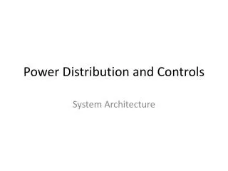
Power Distribution and Controls System Architecture
System Architecture - Power Distribution Wall Outlet DC Power Supply 12-36V, DC 120V,60 Hz X Motor Driver Y Motor Driver Z Motor Driver Wall Outlet Main Logic Board 120V,60 Hz Breakout Board 6V Palm Router
System Architecture - Controls Breakout Board - Processes design file, converts file to motor control signals Main logic Board - Monitors all systems (ie halts operation if vacuum table is off, interlock open) Vacuum System Main Logic Board Computer USB Breakout Board Interlock System Motor Drivers - Takes motor control signals and amplifies to usable form to drive motors Router Motor Driver - Takes signal and modifies it for variable speed Router Motor Driver X Motor Driver Y Motor Driver Z Motor Driver
Router Speed Control • Radial motion in our machine will accomplished using a palm router. Different speeds are required for drilling and milling. Here are some options being considered: • Modifying router circuitry • Microcontroller: Using a microcontroller with PWM channel and H-bridge configuration.