Download
1 / 41
420 likes | 555 Vues
This document discusses the MIRI Sensor Chip Assembly (SCA) simulator presented by Steven Beard at the ROE Workshop “Following the Photon.” The simulator focuses on various modes such as the Medium Resolution Spectrograph (MRS) and imager modes, detailing the steps for simulating detector behavior and quantum efficiency. It also covers the use of Python for developing the SCASim with an object-oriented design, making it flexible and adaptable for other JWST detectors. Key features include handling bad pixels, noise simulation, and integration modes.

E N D
The MIRI Sensor Chip Assembly (SCA) simulator Steven Beard UK Astronomy Technology Centre Royal Observatory, Edinburgh, UK ROE Workshop “Following the Photon”, 10-12 October 2011
JWST Instruments and Detectors MIRI NIRCAM NIRSPEC FGS-TFI 3 Si:As detectors 2 HgCdTe detectors 2 HgCdTe detectors 10 HgCdTe detectors
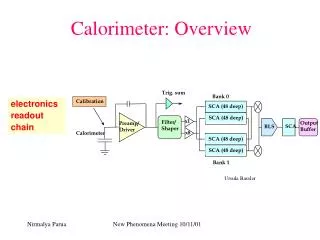
JWST Detector Readout Each integration is made from several non-destructive reads, divided into groups.
MIRI Summary Imager Coronagraph Low Res. Spectrograph • Medium Res. Spectrograph • Short wavelength • Long wavelength
MIRI Modes to be Simulated MIRI has a number of different modes to be simulated, each of which include several common requirements:
MIRI Modes to be Simulated MIRI has a number of different modes to be simulated, each of which include several common requirements: MRS mode is simulated by Specsim.
MIRI Modes to be Simulated MIRI has a number of different modes to be simulated, each of which include several common requirements: MRS mode is simulated by Specsim. All the imager modes are simulated by MirimSim (Rene Gastaud’s presentation?).
MIRI Modes to be Simulated MIRI has a number of different modes to be simulated, each of which include several common requirements: MRS mode is simulated by Specsim. All the imager modes are simulated by MirimSim (Rene Gastaud’s presentation). MTSSim simulates the telescope simulator used for Flight Model (FM) testing.
MIRI Modes to be Simulated MIRI has a number of different modes to be simulated, each of which include several common requirements: MRS mode is simulated by Specsim. All the imager modes are simulated by MirimSim (Rene Gastaud’s presentation). MTSSim simulates the telescope simulator used for Flight Model (FM) testing. All the simulators share the same detector simulation – provided by SCASim.
The MIRI Simulator Suite • Having a suite of simulators ensures that every problem is solved only once. • But we did miss the opportunity to share “simulate targets” and “simulate background”. • SCASim provides a common detector simulation service for the other simulators. • It converts detector illumination information from any MIRI simulator and generates simulated MIRI data in a choice of formats accepted by MIRI pipeline and analysis software.
Required SCA Simulator Steps The SCA Simulator simulates: Quantum efficiency Reference pixels and outputs Bad pixels Dark current and hot pixels Persistence Readout modes Poisson noise and read noise Bias, gain and non-linearity Cosmic ray effects Subarray (window) modes The simulation is controlled by: Input parameters e.g. Readout mode Configuration information e.g. Detector properties Configuration measurements e.g. Dark current vs temperature Calibration data e.g. Bad pixel map X X X X
Design Decisions • I used an Object-Oriented design that would make SCASim more flexible and reusable. • I also wrote the simulator in Python – an object-oriented language with several useful scientific and array processing add-ons (numpy, scipy, matplotlib, pyfits, etc…) • Since the JWST detector readout modes are very similar, I chose to make the SCASim workable with any JWST detector – not just the MIRI detectors. • So ngroups ≠ nframes. Useful for NIRCAM and NIRSPEC as well? • I also chose to encapsulate as much of the detector information in parameter files, rather than in software constants. • By modifying these parameters and/or the class methods, SCASim could be adapted to similar kinds of detector. • The simulator modules were developed along with unit tests. • This ensured that changes didn’t generate unwanted side effects.
SCASim Design Name of class The SCA simulator has an object-oriented design. The core of the simulator is a Detector Array class. The operational interface is generic: All detectors are illuminated, reset, integrated and read out, or can be hit by a cosmic ray. The detailed implementation of the methods simulates the effects of the MIRI detector. This makes the design adaptable and reusable. Attributes Operations
SCASim Design The detector uses a helper class, the Poisson Integrator, which encapsulates the Poisson statistics. Other associated classes are used to describe detector characteristics, such as bad pixels, hot pixels, dark current and quantum efficiency.
SCASim Design Each detector may be read out by one or more amplifiers (4 in the case of MIRI + ref. output).
SCASim Design Each detector may be read out by one or more amplifiers (4 in the case of MIRI + ref. output). Each amplifier is responsible for reading a particular slice (or zone) on the detector surface. Each amplifier has an associated gain, linearity and read noise. Note that dark current and read noise are derived from a generic “Measured Variable” class, used to described laboratory measurements (in this case measuring how dark current and read noise vary with temperature).
SCASim Design Each detector may be read out by one or more amplifiers (4 in the case of MIRI + ref. output). Each amplifier is responsible for reading a particular slice (or zone) on the detector surface. Each amplifier has an associated gain, linearity and read noise. Note that dark current and read noise are derived from a generic “Measured Variable” class, used to described laboratory measurements (in this case measuring how dark current and read noise vary with temperature).
SCASim Design The detector and the amplifiers can both be hit by cosmic rays during an integration, depending on the integration time and their target area. A Cosmic Ray Environment class describes the cosmic ray environment (solar condition etc…), and can generate Cosmic Ray events. Cosmic ray events are selected from a library of simulated events created by Massimo Roberto at STScI (for all JWST detectors).
SCASim Design The SCA simulator also defines classes describing how an exposure is constructed from a series of integrations. The Integration class sequences the reset/integrate/readout operations in the Detector Array. An illumination map describes the intensity and wavelength of the illumination across the detector surface.
SCASim Design Finally, these additional classes show how the contents of the input file are distributed, and how the data associated with each exposure is written to an output file. The Sensor Chip Assembly class manages the simulation and provides a selection of interfaces to the outside world (not shown here).
SCASim Demonstration.Start with some test illumination data. Wavelength data Intensity data
SCASim Experience Good Bad Too many inputs. Nobody has yet edited the configuration files or provided their own calibration files. But the simulation is only as good as the calibration and configuration info. given to it. Only known effects can be simulated. The underlying causes of the “first and last integration effect” and the “pixel lag” effect are not yet known. Perhaps caused by leaving detectors too long without flushing? Subarray vs full frame. But the simulator can help investigate such effects by trying out ideas. • OO design made SCASim highly flexible and reusable. • Rapid development time. • Additional effects (such as variable dark current and persistence) were easy to add. • Now a useful tool adaptable for other detectors. • SCASim made successful predictions for MIRI FM testing. • Expected S/N and exposure times. • Effect of cosmic ray hits. • It also helped development and testing of analysis software. • DHAS cosmic ray detection
The MIRI Sensor Chip Assembly(SCA) Simulator - Summary • What does it do? • It simulates the behaviour of the MIRI detector chips and focal plane electronics. • This simulation is common to all MIRI simulators, so it saves duplication of effort. • What is it for? • MIRI observation planning. • MIRI Flight Model test planning. • JWST Pipeline development and testing. • Design Features • OO design, written in Python. • Highly adaptable and reusable. • Valid for all JWST detectors – could be adapted for other instruments.