UEET 604 Fuel Cell
UEET 604 Fuel Cell. Solid Oxide Fuel Cell Lecture # 6, December 2, 2010. Pradip Majumdar Professor Department of Mechanical Engineering Northern Illinois University DeKalb, IL 60115. Fuel Cell Operating Principles. A fuel cell consist of two porous

UEET 604 Fuel Cell
E N D
Presentation Transcript
UEET 604 Fuel Cell Solid Oxide Fuel Cell Lecture # 6, December 2, 2010 Pradip Majumdar Professor Department of Mechanical Engineering Northern Illinois University DeKalb, IL 60115
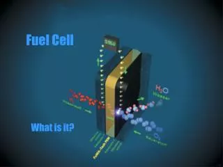
Fuel Cell Operating Principles • A fuel cell consist of two porous electrodes separated by an ion-conducting electrolyte. • A direct hydrogen and oxygen contact and combustion is avoided and replaced by two electrochemical half reactions at two electrode-electrolyte interfaces. • The electrochemical reactions at the anode and cathode sides take place simultaneously producing electricity, and water and heat as the only by-products when hydrogen is used as the fuel. • The free electrons pass through an external circuit, producing power.
Major Challenges For Fuel Cell Commercialization • Improve cell design and efficiency • Increase operating current and power density • Reduce cost (Material and Manufacturing) • Increase reliability and durability of some of the key components such as - Membrane Electrode Assembly (MEA) - Interconnect/ Bipolar Plates - Thermal Heat Management Components - Seals
Solid Oxide Fuel Cell • Cathode reaction: • At the cathode, the reduction of oxygen takes place with the formation of a negatively charged oxygen ion. • The oxygen ion transports through the solid oxide ion conducting membrane electrolyte towards the anode • Anode Reaction: • At anode it combines with hydrogen gas producing water and electrons that travels to the cathode side through the external electrical circuit. Overall reaction:
All solid components Compactness Flexible in fuel types No electrolyte depletion No corrosion of FC components by liquid Reaction zone has two-phase solid-gas interface Attractive Features SOFC • High temperature operation • No use of expensive metal catalyst • High temperature provides better system match • Provides high quality waste heat for cogeneration • Lower activation losses • Better system match results in higher overall conversion efficiencies - 60%
Simpler fuel processing process - May not need the expensive steam reforming and shift conversion • Allows internal reforming of hydrocarbon fuels to produce hydrogen and carbon monoxide • More tolerant to the presence of impurities in the reactant gases Disadvantages • Higher Ohmic losses • Restrictions on materials for interconnect/Bipolar plates, seals and thermal components
DOE-SECA goal for coal-based SOFC power system for distributed based on IGFC SECA - Solid State Energy Conversion Alliance
SOFC Cell Designs • Tubular design • Circular design with center • manifold • Advantages - The concept of one closed end of the tube eliminates the need for gas seals between cells - Can provide robust ceramic structure for the cell • Disadvantages - Leads to a relatively long current path around the circumferences of the cells, resulting in higher internal resistances.
Planar Design • Sequential cells- integrated planar • Simple in design • Most popular • Flow configurations: Co-flow, counter flow or cross flow
Advantages of Planar Design - simpler in manufacturing of the flat components - Potential for higher power densities Disadvantages of the Planar Design - Necessity of sealing to avoid crossover of reactant gasses. - increased risk of cell fractures, particularly during thermal cycling
Planner SOFC MEM Planar SOFCs MEM are generally manufactured in three different configurations • Electrolyte supported cell • (Basic design – 1000C) • Anode supported cell • - Reduced temperature • - 600-800C • - thins electrolyte • Cathode supported cell
Anode • The most common anode material is Nickel-Zirconium Cermet or a mixture of Nickel and yttria–stabilized zirconium (Ni-YSZ) with 30% Ni. • The nickel serves as the catalyst for anode reaction and as electron conductor. • The typical thickness of the anode is generally in range of 40-100 μm. • In recent times a thicker anode that supports a thinner ceramic electrolyte is also available.
Cathode • Most commonly used cathode materials are lanthanum manganite (LaMno3), strontium doped lanthanum manganite (LaSrMno3 ) or LSM, lanthanum strontium cobalt ferrite (LaSrCoFeO). • These materials has good catalyst properties and good electronic conductivity
Electrolyte • The state-of-the-art ceramic electrolyte material is yttria stabilized zirconia (YSZ) - YSZ has highest oxide ion conductivity than any other materials: - lowest electronic conductivity, lowest gas permeability to prevent gas cross over losses. - typical composition contains 8 % Yttria (y2O3) mixed with Zirconia (ZrO2) for temperature of 800-1000 C. Yttria introduces high concentration of oxygen vacancies into zirconia crystal structure and results in a higher ion mobility.
Electrolyte • Current research effort is to develop materials with reduced thickness and reduce operating temperature range of the order of • One such new material is Ce0.9Gd0.1O1.95 (CGO) that operates at lower temperature range while maintaining a sufficient high ionic conductivity.
Thermodynamic Model Reversible Potential: Gibb’s Free Energy: = -2E-05*(T3) + 0.042*(T2) + 23.313*T – 239015
Nernst Equation Include effect of variation in gas concentrations
Butler-Volmer Equation for Electrochemical Kinetics Thelocal current density distribution is calculated by using Butler-Volmer equation Where, i0 = exchange current density η = over potential n = number of electrons = Anodic transfer co-efficient = Cathodic transfer co-efficient • The exchange current density and transfer coefficient represents the electrochemical kinetic parameters.
Transport Model Detail components of heat and mass fluxes across the SOFC fuel cell Heat flux Mass flux Membrane Anode Cathode Anode Channel Cathode Channel MEA with bi-polar plate with flow channels
Gas Channels Mass and Momentum: Navier-Stokes Equation Energy: Mass Concentration:
Gas flow in Porous Electrodes Pressure driven flow through a porous media is given by Brinkman’s equation Effective viscosity of the gas in the porous media
Gas Diffusion Layer-Electrode Continuity: Momentum: Mass Transport: Heat Transfer:
Membrane Transport Equation Mass Transport Heat Transport
Reactant Gas Consumptions • Consumption rates at catalyst-electrode interfaces are specified as follows: Cathode Layer: Anode Layer: Oxygen Gas Hydrogen Gas Water Generation
Activation losses • Activation losses are dominant at the low power densities due to the sluggish electro-kinematics. • The activation losses are directly proportional to the rate of electrochemical reaction. • Activation losses are dominant at the low power densities at lower temperatures. • For dominant cathode overpotential, a simplification of Butler-Volmer equation leads tothe activation losses as Where Xo2 - oxygen concentration along electrode-electrolyte interface
Ohmic Loss Ohmic losses occur due to the resistance to the ionic flow and electronic flow through the electrolyte and electrodes respectively given as Where is constant characterizing the electrolyte material and given as
Mass Transfer Losses Mass transfer losses occur at high current densities due to insufficient supply of the gases. At the higher current densities the fuel supply may not sufficient enough to maintain oxygen concentration at electrode catalyst layer to a positive level to sustain the reaction. This is primarily affected by the gas flow field design in terms of pressure drop and mass transfer effectiveness. The mass transfer loss is given by Where = limiting current density
Heat Generation in Fuel cell • A fraction of the fuel energy is converted into heat within the fuel cell due to number of irreversibilities associated with the activation losses, mass transfer losses, and Ohmic losses for resistances to ion and electrons flows. • This heat energy results in a temperature distribution within the fuel cell and affects the cell’s operating conditions. • This waste heat has to be removed continuously in order to ensure a near isothermal operation of the fuel cell, • A thermal management system is essential to maintain cell temperature and for better overall efficiency of the fuel cell power generation system.
The total heat generation due to electrochemical reaction is given as For single cell Reversible Heat Generation Irreversible Heat Generation Irreversible Heat Generation due to Ohmic heating only For a single cell
Hydrogen Concentration PEMFC (a) 0.5 Amp/cm2 (b) 1.0Amp/cm2 (c)1.5Amp/cm2
Hydrogen Concentration - SOFC • Strong variation along the length of the channel • Strong two-dimensional variation at the anode-membrane interface and around the land areas.
Oxygen Concentration Across the SOFC • Show similar strong variation along the length of the channel and two-dimensional variation in the cell • Steeper variation with increase in current density.
Temperature Distribution - SOFC • Show significantly high temperature level for high current density of 1.5 A/cm2 • Need very effective cooling mechanism to operate around 800-1000 C • Restricts operation at higher current density • Operation of the cell for 0.5 A/cm2 operation show temp rise of 100-150 C • Need to use effective thermal heat management to lower temperature variation in cell
Fuel Cell Power System • Includes fuel gasification, heat and water management subsystems • Gas clean-up includes carbon dioxide and sulphur • There is no practical way to store CO2 for transportation applications • If biodiesel is used as a fuel, SO2 removal is probably unnecessary.
Fuel Cell Hybrid System • Heat from the SOFC can be utilized in a heat engine to increase overall performance • In this hybrid system the fuel cell system is configured as a topping component and the heat engine as the bottoming cycles. • The unspent fuel from the fuel cell, which has a limited fuel utilization, is burned in a combustion chamber.
There are number possible bottoming cycle: - steam or organic Rankine cycle - gas turbine cycle - combination of the two. • Easiest path for the transfer of the exhaust heat is through a heat Exchanger with fuel cell operating at atmospheric conditions. • This is achieved using a steam cycle or with an indirectly fired gas turbine cycle. • Another alternative integration is achieved with a pressurized SOFC where the hot gasses are expanded directly in a gas turbine.
Summary - Fuel cell is a potential alternative power generation system with increased efficiency, lower consumption of conventional fuel, and reduced carbon emission. - Transport phenomena plays a critical role in the design and development of fuel cells - Thermal management is critical for improved performance of a fuel cell power generation system
Summary (Continued) - Bipolar plates with integrated gas flow channel plays a important role in the heat dissipation, maintaining fuel cell operating temperature, thermal heat management and performance of the fuel cell - There are considerable challenges in the design and selection of heat exchangers for high temperature fuel cell power generation system