Plant Layout
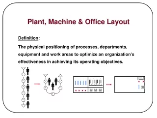
Plant Layout. A Systematic Layout Planning (SLP) Approach Mohamed Iqbal Pallipurath. THE NEED FOR GOOD FACILITIES PLANNING. 1. Plant facilities influence operating costs and profits.

Plant Layout
E N D
Presentation Transcript
Plant Layout A Systematic Layout Planning (SLP) Approach Mohamed Iqbal Pallipurath
THE NEED FOR GOOD FACILITIES PLANNING 1. Plant facilities influence operating costs and profits. 2. Planning allows facilities and its operations (OSHA, ISO 14001, etc.) to comply with laws and/or regulations. 3. Facilities are fixed investments involving high capital-cost expenditures. 4. Facilities are inflexible and long term commitments. 5. The planning, design and construction of facilities require long lead times. 6. Good planning helps to avoid disruptions in production and shipping or delivery.
THE NEED FOR GOOD FACILITIES PLANNING 7. The quality of facilities influences the attitudes of and the ability to attract suitable employees. 8. Industrial facilities must be planned to meet anticipated future requirements yet compete profitably today. 9. Facilities need to be planned for an appropriate degree of flexibility, expandability, versatility… 10. Good plans help management to take advantage of business opportunities that arise. 11. Good planning is an aid to obtain approval and financing monies. 12. Good planning reduces the high materials handling $ resulting from “ad hoc” expansion of plant facilities.
ECONOMIC IMPACT OF FACILITIES PLANNING Resources invested to provide the facilities Consequence on operations of facilities Economic Investment/Consequence ($) Plan20:1 Design2:1 Build & Install1:10 Time
DEFINING PERFORMANCE OBJECTIVES 1. 2. 3.
DEFINING PERFORMANCE OBJECTIVES 4. 5. 6.
TYPES OF MANUFACTURING LAYOUT CONFIGURATIONS I. Product Line Layout Product A B C
CHARACTERISTICS • High volume production • Special purpose machines and material handling equipment • Throughput rates--high • Work-in-process--low • Setup/Run time ratio--low • System is very inflexible • Control is relatively simple
TYPES OF MANUFACTURING LAYOUT CONFIGURATIONS II. Flow Line Workcell T T T T = turningD = drillingM = millingCG = center grindingSG = surface grinding M M T M D D M D SG CG CG D SG GOAL: GAIN the advantages and efficiency of high volume production in a LOW/MEDIUM VOLUME (FLEXIBLE) ENVIRONMENT.
Workstationm Bufferm GT-FLOW LINE WORKCELL CHARACTERISTICS Workstation1 Workstation1 Buffer1 Buffer2
GT-FLOW LINE WORKCELL CHARACTERISTICS 1. Processes GT-based families of parts with frequent job change-over and small to medium batch sizes 2. Piece by piece (continuous flow) processing/movement 3. No backtracking in sequence flow, but machine skipping does occur 4. Accommodates flexible-type automation: CNC machines, robots for part handling 5. Finite buffers (resulting in machine blocking and starvation
TYPES OF MANUFACTURING LAYOUT CONFIGURATIONS III. Cellular Manufacturing (GT Workcell)
CHARACTERISTICS 1. Dissimilar processes/machines 2. Similar parts (families) run in small to medium batch sizes 3. Mini - job shops
Process(Functional) Layout Sawing Turning S S S T T T “Shaft” Milling S S S T T T M T T T Grinding M G G G M Heat Treating G G G HT HT Boring Gear Cut HT B B GC GC B B GC GC
Characteristicsof Process Layouts • Low Volume, High Variety Production with Random Routing (Spaghetti-Like Flow) • General Purpose Machines-- • Machine setups are frequent and long • Work-In-Process -- High • Throughput Rates tend to be Low • Material Handling -- High • Operator Utilization -- Low? • Throughput Times (Lead Time) -- High • System is Very Flexible, produces many different types of parts: gears, shafts, pinions, housings, clamps, etc.
THE P-Q CURVE (High) Product A Product B Product C Q Etc. P (Q) Volume or Quantity (Low) (Low) (High) (P) Variety
Part Volume/Variety Relationships with Manufacturing Systems Configurations (High) ProductLine G.T.FlowlineWorkcell PartVolume G.T.ManufacturingWorkcell Functional(Job-Shop) (Low) Part Variety (Low) (High)
MATERIAL FLOW Importance of Material Flow Properly Planned Material Flow Effective Arrangement of Facilities Efficient Operations Profitability/Viability
Efficient Operations Involve: 1. Good utilization of floor space 2. Reduced materials handling 3. Appropriate equipment utilization 4. Safety 5. Less congestion 6. Less wasted time/efforts 7. Flexibility
MATERIAL FLOW KEY QUESTIONS 1. What is the most effective sequence of moving materials? Eliminate? Combine? Improve? Change Order? 2. What is the intensity and direction?Need to visualize the flow
FLOW OF MATERIAL vs P-Q MIX LAYOUT TYPE I Product LineII Flow Line WorkcellIII G.T. WorkcellIV Functional I II III IV
TYPE I Casting Sheet Steel 4 Tons 10 Tons 0-4 Turn 0-1 Blank 3.3 Tons 9 Tons Turnings0.7 Tons Offal1 Ton 0-5 Drill 0-2 Form 9 Tons 3 Tons Turnings0.3 Tons 0-3 Trim Storage 7 Tons Bolts Scrap2 Tons 10.5 Tons 0-6 Assemble/Inspect Operation Process Chart showing intensity of material flow and the out-flow of chips and scrap. (Muther, SLP)
TYPE II Operation Part or Product A B C D Saw 1 1 1 Center 2 2 2 1 Turn * 3 3 4 2 Heat Treat 4 3 Grind 5 4 3 Mill 5 5 4 Multi-Product Process Chart *Shows problem flow to be resolved by design engineering and manufacturing engineering
TYPE III Parts Machines 5 8 7 12 13 1 10 2 11 14 3 15 4 9 6 4 1 6 Exceptions 8 3 9 2 14 12 5 7 13 11 10 Part-Machine Matrix ofProduction Flow Analysis
TYPE IV Turn Hob Slot Broach Heat Treat Drill Inspect Wash Mill Store TO FROM 1 2 3 4 5 6 7 8 9 10 TOTALS Turn 1 3 3 6 1 5 1 = - - - 26 160 232 2 631 684 Hob 2 7 5 1 - = - - - - - 262 576 10 Slot 3 - - = - - - - - - - Broach 4 1 - - - - - - - - 20 Heat Treat 5 1 7 5 1 - - - - - - 2 414 22 12 Drill 6 9 - - - - = - - - - 752 Inspect 7 1 5 3 - - - - = - - 8 576 910 Wash 8 1 3 - - - - - - - = - 12 12 Mill 9 - - - - - - - - = - Store 10 - - - - - - - - - = TOTALS FROM-TO CHART Number of Parts x y Number of Pieces
RANK THE FLOWS A KEY A:E:I:O:U: Absolutely NecessaryEspecially ImportantImportantOrdinaryUnimportant E I 500 1000 1500 2000 2500 3000 3500 4000 4500 FLOW - OF - MATERIAL INTENSITY O U ActivityPair(Route) 8-13 1-3 3-4 8-15 3-12 11-15 10-13 3-7 7-15 1-14 4-12 4-9 4-15 1-7 2-3 11-15 3-5 1-4 1-12 2-8 11-9 Seq.No. 1 2 3 4 5 6 7 8 9 10 11 12 13 14 15 16 17 18 19 20 21
NON-FLOW (CLOSENESS) RELATIONSHIPS Flow based on routings is not the sole basis for layout arrangements. Adapted from Muther
NON-FLOW (CLOSENESS) RELATIONSHIPS Other Factors • Supporting Services • Tool Room (not routed) • Rest Areas • Central Coolant Tanks • Shop Superintendent’s Office Adapted from Muther
NON-FLOW (CLOSENESS) RELATIONSHIPS Other Factors • Separation of Areas • Welding away from assembly • Outside Doors / Separate / N/C DirtyDangerous DelicateHigh Pop Separate Adapted from Muther
NON-FLOW (CLOSENESS) RELATIONSHIPS In some cases, flow is simply not important No Significant Flow • Service, Repair, Tool Room • Jewelry (one load per week) Adapted from Muther
1 1 Punch Press 2 I 3 2 AuxiliaryPunch Press 1 U RELATIONSHIP CHART 4 D U 5 3 Drilling 2 U U 6 I U U 7 4 Grinding 2 I U U 8 U 2 U U A 9 5 GeneralFabrication E U I 2 E 10 U 2 U O 2 O 2 I 11 6 Wet Tumble U I 2 O 2 U 2 O 12 U I 2 O 2 O U 3 I 13 7 SpecialProduction I 2 O 2 A 2 O O 4 14 E 2 U 2 U 2 O 3 O 4 15 8 Raw MaterialStorage 2 I U I 3 O 4 U 2 E E 3 U 4 9 In-ProcessStorage U 2 O 5 X This block shows relation between “1” and “3” U U 3 I 6 10 Assembly U U 4 O U 1 11 Shop Toilet 3 U O 2 12 Shop Office andTool Room 4 3 13 14 Importance of Relationship (top) 15 Reasons in Code (bottom) Adapted from Muther
RELATIONSHIP CHART Codes Code CLOSENESS Value A E I O U X Absolutely Necessary Especially Important Important Ordinary Closeness OK Unimportant Undesirable 4 3 2 1 0 -1 “Closeness”Rating Adapted from Muther
RELATIONSHIP CHART Value REASON 1 2 3 4 5 6 7 8 9 Equip. used by same persons Movement of material Movement of personnel Supervision and/or support Require same utilities Noise and dirt Reasons behind the “Closeness” Value Adapted from Muther
RELATIONSHIP DIAGRAMS Conventions for diagramming activity relationships Vowel Letter No. Value No. of Lines Closeness Rating Color Code A 4 Absolutely Necessary Red** E 3 Especially Important Orange Yellow** I 2 Important Green** O 1 Ordinary Blue** U 0 Unimportant Uncolored** X -1 Not Desirable Brown** XX -2, -3, -4, ? Extremely Undesirable Black
PROCEDURE/EXERCISE Dept. No. Sq. Feet Dept. Desc. 1 5,000 Parts Storage E 2 10,000 Ship/Receiving U O U 3 2,500 Welding U I X I E 4 2,500 Testing I I U U X U 5 7,500 Machining A X O I 6 5,000 Assembly U A 7 2,500 Paint Figure 1: Relationship Chart
PROCEDURE/EXERCISE TO FROM 1 2 3 4 5 6 7 1 170 2 50 170 40 3 80 50 20 4 20 120 5 50 20 6 120 7 120 Figure 2: From-To Chart (in Loads per Weeks)
1 Determine Total Flow TO FROM 1 2 3 4 5 6 7 1 50 170 2 170 90 120 3 80 50 20 4 140 120 5 20 6 7
2 Rank the Flows 200 180 160 140 120 Total Flow 100 80 60 40 20 5-7 3-7 3-6 1-2 3-5 2-5 4-7 2-7 4-6 2-3 1-6 0 0 1 2 3 4 5 6 7 8 9 10 11
3 Combine Flow & Non-Flow Relationships Activity Pairs 1-21-31-41-51-61-72-32-42-52-62-73-43-53-63-74-54-64-75-65-76-7 Non Flow: Flow1 to 1 Ratio 30023010220-20-2-2042104 100040401030210033000 Combined Total Points 40027050423-22-1-2075104
4 Rank the Combined Points 10 9 8 7 6 Total Points 5 4 3 2 1 3-5 2-6 1-5 2-7 6-7 2-5 1-2 4-7 2-3 4-6 5-6 1-6 0 3-6 3-4 3-7 0 1 2 3 4 5 6 7 8 9 10 11 12 Activity Pairs
5 Develop Combined Relationship Chart(Flow and Non-Flow) 1 5,000 Parts Storage I 2 10,000 Ship/Receiving E 3 2,500 Welding O XX I A 4 2,500 Testing O O X I 5 7,500 Machining A XX E 6 5,000 Assembly I 7 2,500 Paint
6 Develop Relationship Diagram i Place “A” Relationship Values on Grid ii Add the “E” Relationship Values and Adjust Diagram to Minimize Distance X Flow Value iii Place “A” Relationship Values on Grid
6. Relationship Diagram + + + + + + + + + + + + 4 + 6 + 1 + + + 7 + 2 + 3 + + + + 5 + + A E I O U X XX
7. Measures of Effectiveness S S L D ij ij i j Min Z = L = Load between departments i & j, often measured by the value of the Vowel Letter.A = 4, E = 3, I = 2, O = 1, U = 0, X = -1 ij D = Distance between departments i & j (move only at Right angles) ij *Many Variations of this Concept 8. Space Relationship Diagrams9. Layouts
7. Diagram Score: Department Pair 1-21-31-41-51-61-72-32-42-52-62-73-43-53-63-74-54-64-75-65-76-7 Lij 20014030212-11-1-1043000 Dij 202313121113222311222 Zij 40034030212-32-2-2043000 21
Types of Layouts Product (Q) Number of pieces/part# CM Job-Shop (process) Number of Part Numbers (P)
PRODUCT LAYOUT Product Layout: Continuous Flow Production System Definition: Layout is dictated by the product. (P) Suited to manufacturing processes with single output Equipment arrangement operation sequence High production (volume) items and stable demand, similar products:
PRODUCT LAYOUT • Materials move by units in a product line, not by lots. *? UNIT 1. 2. 3. demand Operations performed at various workstations *The Output is determined by the slowest operation TASK is to BALANCE the workstations in terms of the work done (time) and satisfy the required output. * \
PRODUCT LAYOUT Two Types of Problems: Required Information: Fabrication Lines Assembly Lines (R) Sequence of operations or job elements Time required for each operation or independent element Output required (T) (Q)
EXAMPLE Design a fabrication line to manufacturing a product with the following 7 operations. Initially assume: No scrap losses 100% eff. & 480 min/day 1000 units required per day