Download
1 / 21
230 likes | 419 Vues
ALFRED and ELFR Secondary System and Plant Layout. ALFRED Secondary System. 1. Scope. Secondary system optimized for demonstrating that ALFRED reactor would be able to efficiently produce electric power Important considerations and constraints:

E N D
ALFRED SecondarySystem 1. Scope • Secondary system optimized for demonstrating that ALFRED reactor would be able to efficiently produce electric power • Important considerations and constraints: • Lead temperature never drops to alarming values • ST 182 bar; 450ºC superheated steam • Pipes dimensioning: feed water, main steam and pipes through the containment • Operational Modes: • Normal Mode Efficient electric production • Partial load Mode Partial thermal load operation • By-pass Mode Direct heat transfer through the condenser • Auxiliary heating Mode Lead heating from the secondary system
ALFRED SecondarySystem 2. Main input data • Secondary system main parameters: • Steam Generators: • Outlet pressure: 182 bar (180 bar at inlet of the HP turbine valve) • Inlet pressure: 188 bar • Outlet temperature: 450ºC • Inlet temperature: 335ºC • Steam flow: 192.7 Kg/s. Thermal power 300 MWth • Heat sink: • Mechanical draft cooling tower • Nominal: 18ºC; 60% relative humidity • Extreme summertime (EUR): 37ºC; 60% relative humidity • Extreme wintertime (EUR): -25ºC; 100% relative humidity • Steam turbine group inlet control: throttle control valve • Steam turbine mechanical losses: 0.25% • Deaerator elevation: 22.86 m
ALFRED SecondarySystem 3. Secondary system options • Two turbines HP and LP with three extractions each • Heater fed with main steam (Feedwater Temp. Control Heater - FWTCH) • Three low pressure (LP) preheaters and three high pressure (HP) preheaters • Single train for the HP and LP preheaters • Moisture separator (MS) is included • HPT exhaust pressure of 12 bar
ALFRED SecondarySystem SteamCycleEfficiency: 44,68% Net CycleEfficiency: 41,50% Generator Output: 133 MWe
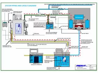
ALFRED SecondarySystem 4. Secondary system layout
ALFRED SecondarySystem 4. Secondary system feasibility study: Normal Mode • Turbine configuration: • HP Turbine and a LP Turbine, with no intermediate stage (typical nuclear configuration) • HP Turbine: 180 bar to 12 bar range, with three extraction lines • Turbine power range for medium turbines (less than 200 MW) • Axial exhaust turbine is chosen for ALFRED
ALFRED SecondarySystem 4. Secondary system feasibility study: Normal Mode
Throttle control valve System is able to lower the load without lowering too much the pressure of the temperature Performance decreases as the load decreases FWTC Heater Valve maintain the feed water temperature (335ºC) ALFRED SecondarySystem 4. Secondary system feasibility study: Partial Load Mode
ALFRED SecondarySystem 4. Secondary system feasibility study: Auxiliary Heating Mode • Only liquid water is not feasible • System with only steam is proposed: • Lead temperature: 380ºC – 400ºC • Steam temperature: 400ºC – 450ºC • Optimum SG inlet pressure? 30 bar
ALFRED SecondarySystem 4. Secondary system feasibility study: By-Pass Mode • Deaerator (operating at atmospheric pressure) fed with main steam • FWTC Heater maintains 335ºC • High FWTC Heater DDA attemperation with condensate water
ALFRED SecondarySystem 4. Secondary system feasibility study: Heat Sink Analysis - Mechanical draft cooling tower - Nominal: 18ºC; 60% relative humidity - Extreme summertime (EUR): 37ºC; 60% relative humidity - Extreme wintertime (EUR): -25ºC; 100% relative humidity Extreme summer Nominal Extreme winter
ALFRED SecondarySystem 5. Main steam and feed water pipes dimensioning • High temperature material: SA-335 Gr91 • Design temperature: 450ºC • Design pressure: 20 MPa
ALFRED SecondarySystem 6. Conclusions • Good performance of the proposed secondary system is demonstrated • Requirements are complied: • High steam cycle efficiency: 44.68% reactor economic viability • Good behavior at partial loads • Minimum FW temperature at SG inlet is well controlled (335ºC) • By-pass operation mode is feasible • Auxiliary heating system is proposed: heating lead from secondary system • Performance at extreme summer and wintertime • SG operational parameters are defined • Pipes dimensioning (SA-335 Gr91) and preliminary track through the containment is proposed
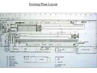
ALFRED PlantLayout Plantsurface: 276x270 m2
ALFRED Reactor Building Supportedoverseismicisolators
The data for the supercritical cycle were: • Steam generator inlet temperature: 335ºC • Steam generator outlet temperature: 450ºC • Steam generator outlet pressure: 24,3 Mpa • Steam Generator pressure for supercritical cycle: 26 MPa ELFR SecondarySystem
Service Building & Operation Support Center Fire Brigade & Fire Water Storage Tank Turbine Building Auxiliary Boiler Reactor Building Cold Machine Shop Independent Spent Fuel Storage Switch Yard Fuel Building Diesel Generators Administration Building Warehouse Access Control Diesel Tank Transformers N2 Plant & Warehouse Visitor Building Condensate Storage Tanks Cooling Towers Dematerialized Tank Pump House Water Storage Tanks Make-Up Pumps House Service Water Building & Water Treatment Effluent Collection Pond ELFR PlantLayout. Option 1 Plant surface: 360 x 450 m²
Service Water Building & Water Treatment Visitor Building Cooling Tower Access Control AdministrationBuilding Pump House Fuel Building Effluent Collection Pond Independent Spent Fuel Storage Fire Brigade & Fire Water Storage Tank Make-Up Pumps House Dematerialized Tank Condensate Storage Tanks N2 Plant & Warehouse Reactor Building Diesel Tank Transformers Cold Machine Shop Warehouse Service Building & Operation Support Center Turbine Building Diesel Generators Switch Yard ELFR PlantLayout. Option 2