Download
1 / 22
250 likes | 518 Vues
ALFRED and ELFR design overview . Technical Workshop to Review Safety and Design Aspects of European LFR Demonstrator (ALFRED), European LFR Industrial Plant (ELFR), and European Lead Cooled Training Reactor (ELECTRA) Joint Research Centre, Institute for Energy and Transport,

E N D
ALFRED and ELFR design overview Technical Workshop to Review Safety and Design Aspects of European LFR Demonstrator (ALFRED), European LFR Industrial Plant (ELFR), and European Lead Cooled Training Reactor (ELECTRA) Joint Research Centre, Institute for Energy and Transport, Petten, the Netherlands, 27–28 February 2013 Luigi Mansani Luigi.mansani@ann.ansaldo.it
Development of a new reactor technology must follow gradual and progressive steps to reach maturity Identification of main issues related to the technology Small scale to Large scale experimental facilities Irradiation tests, fuel and materials development and try to: Exploit full potential of the coolant Include from the beginning Safety in the Design Show sustainability of the fuel cycle Define and evolve a reference conceptual design of the FOAK Introduction
LFR Development • The first step in the development of a Lead Cooled Critical Fast Reactor in Europe started in 2006 with the EU - FP6 ELSY project, on the basis of previous projects already carried out in the frame of projects dedicated to Lead-Bismuth/Lead cooled Accelerator Driven Systems (XT-ADS, EUROTRANS, etc.) • On February 2010 (EU - FP6 ELSY project terminated) a first reference configuration of an industrial size (600 MWe) LFR was available • On April 2010 the LEADER project started its activities with the main goal to: • Develop an integrated strategy for the LFR development • Improve the ELSY design toward a new optimized conceptual configuration of the industrial size plant, the ELFR conceptual design • Design a scaled down reactor, the LFR demonstrator – ALFRED, using solutions as much as possible close to the adopted reference conceptual design but considering the essential need to proceed to construction in a short time frame
PDS-XADS project 5th EU FP (2002-2004) • 50 MW LBE-cooled XADS (MYRRHA) 80 MW Gas-cooled XADS 80 MW LBE-cooled XADS Lead & LBE technology development in Europe
XT-ADS/MYRRHA EFIT Lead & LBE technology development in Europe IP-EUROTRANS project 6th EU FP (2005-2010)
ELSY FASTEF/MYRRHA Lead & LBE technology development in Europe CDT project 7th EU FP (2009-2012) ELSY project 6th EU FP (2006-2010)
From ELSY to LEADER • ELFR Strategy: Maintain the good solutions, change the rest • Spiral SG - specific task in LEADER to address manufacturability issue • Expected advantage of open FA not verified, back to wrapped FA option that permits an easy continuous monitoring in case of flow blockage • Bottom grid introduced, lateral restraint for core and shroud, FAs weighted down by Tungsten ballast • Need to develop alternative DHRs, ICs maintained • ALFRED Strategy: “Demonstration reactor has to be realized in the short term relying on the today available technology. As a consequence, while we should try to design a demonstrator as close as possible to the reference industrial size ELFR, we shall switch (where needed) to proven and available solutions” • Some components of ALFRED different from the design proposed for ELFR • SGs: double wall straight bayonet tubes, continuous monitoring, permits use of SGs tube bundles as part of DHR system, easy coating and/or surface treatment: speed-up to construction • DHRs: Based mainly on isolation condenser of ELFR • Other design options are in general as close as possible to ELFR design
Why LEAD? – Some Advantages • Lead does not react with water or air • Steam Generators installed inside the Reactor Vessel • Very high boiling point (1745°C ), very low vapor pressure (3 10-5 Pa @ 400 °C) • Reduced core voiding reactivity risk • Lead has a higher density • No need for core catcher (molten clad float and breached fuel could float) • Lead is a low moderating medium and has low absorption cross-section • No need of compact fuel rods (large p/d defined by T/H) • Very low pressure losses (1 bar for core, 1.5 bar for primary loop) • Very high primary natural circulation capability natural circulation DHR LEAD COOLANTPASSIVE SAFETY
Why LEAD? – Not Only Advantages High Lead melting point (~ 327 °C) – assure Lead T above 340-350 °C Overcooling transient (secondary side) may cause Lead freezing Corrosion / erosion of structural materials - Slugging of primary coolant Seismic risk due to large mass of lead In-service inspection of core support structures Fuel loading/unloading management by remote handling Steam Generator Tube rupture inside the primary system Flow blockage and mitigation of core consequences
Why LEAD? – Not Only Advantages PROVISIONS High Lead melting point (~ 327 °C) – assure Lead T above 340-350 °C Heating system, design and operating procedures Overcooling transient (secondary side) may cause Lead freezing FW requirement – diversification and redundancy – Really a safety issue? Corrosion / erosion of structural materials - Slugging of primary coolant Coatings, oxygen control, limit flow velocity (Russian approach) Strategy at low oxygen content, Lead chemistry (alternative approach) Seismic risk due to large mass of lead 2-D seismic isolators, vessel hanged, specific design (EU FP7 SILER project) In-service inspection of core support structures Similar to other HLM reactors but high T, all components replaceable Fuel loading/unloading by remote handling Develop appropriate cooling system (active passive back-up) Steam Generator Tube rupture inside the primary system Show no effect on core, provide cover rupture disks to limit max pressure Flow blockage and mitigation of core consequences Hexagonal wrapped FAs – outlet temperature continuous monitoring Full unprotected flow blockage causes cladding damages to a max of 7 FAs
Strategy for Sustainability of Nuclear Energy Present known resources of Uranium represent about 100 years of consumption with the existing reactor fleet Fast neutron reactors with closed fuel cycle have the potential: to multiply by a factor 50 to 100 the energy output from a given amount of uranium (with a full use of U238), to improve the management of high level radioactive waste through the transmutation of minor actinides to provide energy for the next thousand years with the already known uranium resources • Both fast spectrum critical reactors and sub-critical ADS are potential candidates for dedicated transmutation systems • Critical reactors, however, loaded with fuel containing large amounts of MAs might pose safety problems caused by unfavourable reactivity coefficients and small delayed neutron fraction • Core fuelled with only MA (Uranium free) has no Doppler nor Delayed Neutrons
FP + losses MOX first loads LFR Adiabatic Reprocessing MOX equilibrium Unat/dep All Actinides Fabrication Sustainability: Example of Closed Fuel Cycle in Fast Reactors • LFR can be operated as adiabatic: • Waste only FP, feed only Unat/dep • Pu vector slowly evolves cycle by cycle • MA content increases and its composition drift in the time • LFR is fully sustainable and proliferation resistant (since the start up) • Pu and MA are constant in quantities and vectors • Safety - main feedback and kinetic parameters vs MA content
ALFRED - Design Guidelines ALFRED will be connected to the electrical grid Power close to 125 MWe (300 MWth) ALFRED design should be based as much as possible on available technology to speed up the construction time ALFRED design solution (especially for Safety and Decay Heat Removal function) should be characterized by very robust and reliable choices to smooth as much as possible the licensing process ALFRED Decay Heat Removal System based on passive technology to reach the expected high Safety level
171 Fuel Assembly 4 Safety Rods 12 Control Rods 108 Dummy Element ALFRED - Core Configuration FAs – Same concept of ELFR • Control/shutdown system • 2 diverse, independent and redundant shutdown systems • 1° System for Control and Shutdown - Buoyancy Absorbers Rods passively inserted by buoyancy from the bottom of the core • 2° Shutdown System - Pneumatic Inserted Absorber Rods passively inserted by pneumatic from the top of core
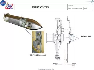
ALFRED - Reactor Configuration MAIN COOLANT PUMP REACTOR VESSEL SAFETY VESSEL FUEL ASSEMBLIES STEAM GENERATOR STEAM GENERATOR MAIN COOLANT PUMP REACTOR CORE Power: 300 MWth Primary cycle: 400-480 °C Secondary cycle: 335-450 °C
157 Inner Fuel Assembly 270 Outer Fuel Assembly 12 Safety Rods 12 Control Rods 132 Dummy Element ELFR – FA and Core Configuration STRATEGY: -“Adiabatic” core power distribution flattened with two zone different hollow pellets diameters
ELFR - Reactor Configuration • Pumps integrated in the SGs • Spiral SGS (8) – once through • Hexagonal Wrapped FAs • FAs extended to cover gas • Core Bottom grid • Inner shroud – lateral restraint • FAs weighted down by Tungsten ballast (pumps off) • FAs kept in position by top springs (pumps on) • 4 Isolation condenser connected to SGs (DHR1) • 4 Dip coolers immersed in the main vessel (DHR2) Power: 1500 MWth Primary cycle: 400-480 °C Secondary cycle: 335-450 °C
Decay Heat Removal Systems Several systems for the decay heat removal function have been conceived and designed for both ELFR and ALFRED Onenon safety-grade system, the secondary system, used for the normal decay heat removal following the reactor shutdown Twoindependent, diverse, high reliable passive and redundantsafety-related Decay Heat Removal systems (DHR N1 and DHR N2): in case of unavailability of the secondary system, the DHR N1 system is called upon and in the unlike event of unavailability of the first two systems the DHR N2 starts to evacuate the DHR DHR N1: Both ELFR and ALFRED rely on the Isolation Condenser system connected to 4 out of 8 SGs DHR N2: ELFR rely on a water decay heat removal system in the cold pool ALFRED rely on an Isolation Condenser system connected to the other four SGs Considering that, each SG is continuously monitored, ALFRED is a demonstrator and a redundancy of 266% is maintained, the Diversity concept could be relaxed DHR Systems features: Independence obtained by means of two different systems with nothing in common Diversity obtained by means of two systems based on different physical principles Redundancy is obtained by means of three out of four loops (of each system) sufficient to fulfil the DHR safety function even if a single failure occurs Passivity obtained by means of using gravity to operate the system (no need of AC power)
ALFRED Secondary System • Power conversion system based on superheated cycle • with dual turbine configuration, three extractions in the HP and in the LP with an axial outlet • Net cycle efficiency greater than 41%
ELFR Secondary System Power conversion system based on same ALFRED concept
ALFRED Thank you for your attention