Download
1 / 31
310 likes | 444 Vues
The Medium Energy Beam Transport Line (MEBT). 29 November 2010, DL Ciprian Plostinar. Outline. MEBT Optics. The Chopping Scheme. MEBT Components. New MEBT Optics. The Front End Test Stand @ RAL. LEBT. MEBT. Ion Source. RFQ. 3 MeV High Current Operation (60 mA )

E N D
The Medium Energy Beam Transport Line (MEBT) 29 November 2010, DL CiprianPlostinar
Outline • MEBT Optics • The Chopping Scheme • MEBT Components • New MEBT Optics
The Front End Test Stand @ RAL LEBT MEBT Ion Source RFQ • 3MeV • High Current Operation (60 mA) • High duty cycle RFQ MEBT and chopper LEBT H−Ion Source
Lost/partially lost linac bunches The Chopping Principle • The Beam Chopper • Produces gaps in the bunched beam • Enables low beam loss operation during injection in accumulator rings • Low energy (2.5 – 3 MeV ), high duty cycle (~1-10%) high quality beam chopping is important to demonstrate. Ring RF buckets at low frequency (a few MHz) Linac bunches at high frequency (324 MHz)
The Fast-Slow Chopping Scheme • To achieve perfect chopping a very high speed chopper is required (<2 ns) • Unchopped bunches – beam loss at injection • Partially chopped bunches – beam loss along the linac • The Fast-Slow Chopping Scheme: • The Fast Chopper: • Transition Time: 2 ns • Duration Time: 12 ns • Electrode Length: ~ 450 mm • Chopper Potential: +/- 1.3 kV • The Slow Chopper: • Transition Time: 12 ns • Duration: 250 – 0.1 ms • Electrode Length: 450 mm • Chopper Potential: +/- 1.5 kV
Beam Optics – Existing Designs • CERN Linac4 MEBT • J-PARC MEBT • SNS MEBT
FETS MEBT Beam Optics • Two opposing requirements: • Provide strong transverse focusing • Provide sufficiently long empty drifts for the choppers
FETS MEBT Beam Optics Beam Envelopes Slow Chopper Fast Chopper 21.8 mm centre separation 2.6 mm gap between the 99% emit ellipses. 23.2 mm centre separation 4.5 mm gap between the 99% emit ellipses.
MEBT Components - Chopper Electrodes - Chopper Electrode Design Short length helical prototype Short length planar prototype
MEBT Components - Re-Bunching Cavities - • 2D EM Simulations • Different possible geometries were evaluated and a single gap pillbox-type cavity with nose cones was adopted. • Initial simulations were performed with Superfish and a VB script was developed that allowed multiple optimisations to be carried out in order to chose the best geometry satisfying the design constraints. • A summary table with the cavity parameters can be seen below. In addition, other studies have been performed, like the frequency dependence of different geometry choices, the variation of the peak electric field with gap length, etc. • The mechanical drawing of the structure can now begin for the construction of a cold model.
MEBT Components - Re-Bunching Cavities - • 3D EM Simulations • Performed with HFSS and Microwave Studio. • Aimed at problems that lack cylindrical symmetry,. • Code comparison. • 3D simulations are time-consuming and the accuracy of the results depends on the number of mesh nodes.
MEBT Components - Quadrupoles - • A standard EMQ design is being analysed. • A hybrid quadrupole option is under investigation. The main aim is to address the requirement for a compact design, combined with a limited ability to adjust the field gradient. • The hybrid quadrupole will be a concentric combination of PMQ and laminar conductor EMQ types(Lambertsonquadrupole). • Initial estimations indicate that the range of adjustment offered by the laminar EMQ is limited and alternatives are being investigated.
MEBT Components - Beam Dumps & Diagnostics • A dedicated beam stop is currently being designed. • At10% duty cycle it is expected to dissipate a beam power of ~ 18 kW. • Pure Aluminium is the preferred material due to its excellent radiation performance, although its poor mechanical properties make the design more challenging from an engineering point of view. • If proven successful, a similar solution could be adopted for the chopper beam dumps. • A movable diagnostics bench is foreseen for the commissioning stage of the MEBT. It will measure the beam profile, beam position, emittance and halo (transverse plane), as well as transmission, average beam energy, energy spread , bunch shape profile and chopping efficiency (longitudinal plane). • In addition a permanent comprehensive set of diagnostics is envisaged for the entire line. It includes beam position monitors, current monitors, steering and profile monitors. • A laser based non-destructive emittance measurement instrument will be located at the end of the MEBT.
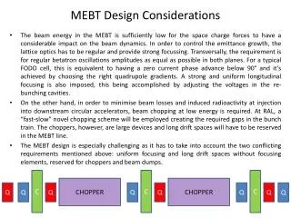
Alternative MEBT Design • RFQ, DTL – focusing elements adjusted -> smooth beam phase advances • FODO structure – high quality beam transport if the zero current phase advance/period < 90° (envelope stability criteria) RFQ MEBT DTL ? C C C CHOPPER CHOPPER Q Q Q Q Q Q Q Q Q Q
MEBT Design Considerations • New MEBT Optics • Regular lattice between the RFQ and the DTL (strong focusing, smooth phase advance variation - FODO). • Multiple short beam choppers. • The choppers can’t be placed anywhere, but at positions where the kicks will add up. • For a 90° phase adv/cell (FODO) the kickers should be placed in every other cell. • Chopping in both planes (vertical & horizontal). • Deflecting alternatively up and down (left - right). • One can make the MEBT as long as necessary to get the required deflection.
FODO Lattice • Advantages • Small emittance growth • Zero Losses • No partially chopped beam • ~20% less voltage required on the chopper plates in current configuration (coverage factor not taken into account) • Chopped beam distributed on several beam dumps • Easier DTL matching • Can add more cells if required, to reduce the voltage
FFDD Lattice • Advantages • Similar to FODO + • Fewer chopper plates than FODO • Less voltages required
Comparison with Existing designs • Solenoid MEBT • FETS MEBT
Conclusions • The MEBT work is progressing well. • Beam dynamics simulations indicate that the line can match and transport a beam from the RFQ, through the chopping structure and into a downstream accelerator. • The chopping efficiency is above 99% and losses are minimal. • The MEBT components are currently being designed and prototyped. • The following steps will include a detailed engineering analysis of the physics design. • New MEBT optics under consideration
Other Work • End to end beam dynamics • RAL, J-PARC, “Distributed” MEBT designs • Important to compare the effectiveness of various methods of operation. • Simulation study of high intensity beam dynamics and beam transport when the various MEBT designs are each fed into the same J-PARC linac structure. DTL Front End SDTL ACS 50 MeV 180 MeV 400 MeV 3 MeV 324 MHz 972 MHz