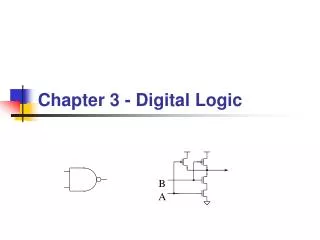
Chapter 3 Digital Logic Structures
Chapter 3 Digital Logic Structures. Transistor: Building Block of Computers. Microprocessors contain millions of transistors Intel Pentium II: 7 million Compaq Alpha 21264: 15 million Intel Pentium III: 28 million Logically, each transistor acts as a switch


Chapter 3 Digital Logic Structures
E N D
Presentation Transcript
Transistor: Building Block of Computers • Microprocessors contain millions of transistors • Intel Pentium II: 7 million • Compaq Alpha 21264: 15 million • Intel Pentium III: 28 million • Logically, each transistor acts as a switch • Combined to implement logic functions • AND, OR, NOT • Combined to build higher-level structures • Adder, multiplexor, decoder, register, … • Combined to build processor • LC-2
Simple Switch Circuit • Switch open: • No current through circuit • Light is off • Vout is + 5V • Switch closed: • Short circuit across switch • Current flows • Light is on • Vout is 0V Switch-based circuitscan easily represent two states: on/off, open/closed, voltage/no voltage.
N-type MOS Transistor • MOS = Metal Oxide Semiconductor • two types: N-type and P-type • N-type • when Gate has positive voltage,short circuit between #1 and #2(switch closed) • when Gate has zero voltage,open circuit between #1 and #2(switch open) Gate = 1 Gate = 0 Terminal #2 must be connected to GND (0V).
P-type MOS Transistor • P-type is complementary to N-type • when Gate has positive voltage,open circuit between #1 and #2(switch open) • when Gate has zero voltage,short circuit between #1 and #2(switch closed) Gate = 1 Gate = 0 Terminal #1 must be connected to +2.9V.
Logic Gates • Use switch behavior of MOS transistorsto implement logical functions: AND, OR, NOT. • Digital symbols: • recall that we assign a range of analog voltages to eachdigital (logic) symbol • assignment of voltage ranges depends on electrical properties of transistors being used • typical values for "1": +5V, +3.3V, +2.9V • from now on we'll use +5V
CMOS Circuit • Complementary MOS • Uses both N-type and P-type MOS transistors • P-type • Attached to + voltage • Pulls output voltage UP when input is zero • N-type • Attached to GND • Pulls output voltage DOWN when input is one • For all inputs, make sure that output is either connected to GND or to +,but not both!
Inverter (NOT Gate) Truth table
NOR Gate Note: Serial structure on top, parallel on bottom.
OR Gate Add inverter to NOR.
NAND Gate (AND-NOT) Note: Parallel structure on top, serial on bottom.
AND Gate Add inverter to NAND.
Fundamental Properties of boolean algebra: Commutative: • X + Y = Y + X • X . Y = Y . X Associative: • ( X + Y) + Z = X + (Y + Z) • ( X . Y) . Z = X . (Y . Z) Distributive: • X . (Y + Z) = (X . Y) + (X . Z) • X + (Y . Z) = (X + Y) . (X + Z) Identity: • X + 0 = X • X . 1 = X Complement: • X +X’ = 1 • X . X’ = 0
X+1 • X+0 • X.X • X.1 • X.0 • X+XY
More than 2 Inputs? • AND/OR can take any number of inputs. • AND = 1 if all inputs are 1. • OR = 1 if any input is 1. • Similar for NAND/NOR. • Can implement with multiple two-input gates,or with single CMOS circuit.
Practice • Implement a 3-input NOR gate with CMOS.
Logical Completeness • Can implement ANY truth table with AND, OR, NOT. 1. AND combinations that yield a "1" in the truth table. 2. OR the resultsof the AND gates.
A B C Practice • Implement the following truth table.
X Y Z Output Another example: We want to build a circuit that has 3 binary inputs. This CKT is On if the inputs are X’Y’Z or X’YZ’ .
A + B A + B XOR gate: • A XOR B= A.B’+A’.B • A + B A B A B A.B’+A’.B
DeMorgan's Law • Converting AND to OR (with some help from NOT) • Consider the following gate: To convert AND to OR (or vice versa), invert inputs and output. Same as A+B
OR Truth table • DeMorgan Law: • A+B= (A’ . B’)’ • A.B=(A’+B’)’ AND Truth table
Build the following logical expression using AND, Not Gates only: • F=X.Y+Z’ =((X.Y)’.Z’’)’ =((X.Y)’.Z)’ Another example: • F= XYZ+Y’Z+XZ’ = ( (XYZ)’.(Y’Z)’.(XZ’)’ )’
From Demorgans law • A+B= (A’.B’)’ • (A+B)’= (A’.B’)’’=A’.B’ • A.B= (A’+B’)’ • (A.B)’= (A’+B’)’’=A’+B’
Simplify the following boolean expression • F= (A’BC + C + A + D )’ • = ( A’BCC’ + (A’BC)’C +A+D)’ • = ( A’B. 0 + (A’BC)’C +A+D)’ • = ( 0 + (A’BC)’C +A+D)’ • = ( (A+B’+C’)C+A+D)’ • = ( AC+B’C+C’C+A+D)’ • = ( AC+B’C+ 0 + A +D)’ • = (AC+A + B’C + D)’ • = ( A + B’C + D)’ • = A’ (B’C)’ D’ • = A’ D’( B+C’) • = A’BD’+A’C’D’
Simplification using boolean algebra: • We have the following truth table for logical circuit and we want to implement this in the minimum number of gates: F=A’B’C+A’BC+AB’C’+AB’C+ABC’ = A’B’C+A’BC+AB’(C+C’)+ABC’ = A’C(B+B’) +AB’ +ABC’ = A’C+AB’+AC’(B+B’) ;we can reuse AB’C’ =A’C+AB’+AC’
Another example: F=A’B’C+A’BC+AB’C+ABC’+ABC = A’C(B+B’)+AB’C+ABC’+ABC = A’C + AC(B’+B) +ABC’ = A’C+AC+ AB(C+C’) =A’C+AC+AB = C(A+A’)+AB = C+AB
Karnaugh Maps • Karnaugh map : is a representation for the truth table in a graphical way, which makes the simplification of any boolean function easier. • For 3 input boolean function the Karnaugh map will be as follows : BC A As we can see, each cell represent one raw of the truth table Next step is to fill the map using the truth table output.
Simplification using Karnaugh: • Let us resolve the previous examples using karnaugh map: BC A F=A’C+B’C+AC’
Resolve the same example in another way: BC F=A’C+AB’+AC’
Assume we have the boolean function F with 4 inputs: • F(A,B,C,D)= ∑ (0,1 ,4, 6, 8,11,13, 15) • Make the truth table for this function • Write the boolean equation for this function (Before simplification) • Simplify this function using karnaugh map technique • Draw the simplified equation.
Summary • MOS transistors are used as switches to implementlogic functions. • N-type: connect to GND, turn on (with 1) to pull down to 0 • P-type: connect to +2.9V, turn on (with 0) to pull up to 1 • Basic gates: NOT, NOR, NAND • Logic functions are usually expressed with AND, OR, and NOT • Properties of logic gates • Completeness • can implement any truth table with AND, OR, NOT • DeMorgan's Law • convert AND to OR by inverting inputs and output
Building Functions from Logic Gates • We've already seen how to implement truth tablesusing AND, OR, and NOT -- an example of combinational logic. • Combinational Logic Circuit • output depends only on the current inputs • stateless • Sequential Logic Circuit • output depends on the sequence of inputs (past and present) • stores information (state) from past inputs • We'll first look at some useful combinational circuits,then show how to use sequential circuits to store information.
Decoder • n inputs, 2n outputs 1 Y0 A 0 1 1 0 0 0 1 1 1 Y1 1 Y2 B 1 Y3
Decoder • n inputs, 2n outputs • exactly one output is 1 for each possible input pattern 2-bit decoder
3x8 decoder 0 1 2 3 4 5 6 7
Build the following truth table using Decoder and OR gate 3x8 decoder 0 1 2 3 4 5 6 7
Multiplexer (MUX) • n-bit selector and 2n inputs, one output 0 1 I0 I1 I2 I3 1 1 0 S1 S0 0 0 0 1
Multiplexer (MUX) • n-bit selector and 2n inputs, one output • output equals one of the inputs, depending on selector 4-to-1 MUX
Full Adder • Add two bits and carry-in,produce one-bit sum and carry-out. • S = A + B + Cin • Cout = A.B+A.C+B.C
Full Adder • Add two bits and carry-in,produce one-bit sum and carry-out. 3x8 decoder 0 1 A B Cin S 2 3 4 5 C 6 7
Combinational vs. Sequential • Combinational Circuit • always gives the same output for a given set of inputs • ex: adder always generates sum and carry,regardless of previous inputs • Sequential Circuit • stores information • output depends on stored information (state) plus input • so a given input might produce different outputs,depending on the stored information • example: ticket counter • advances when you push the button • output depends on previous state • useful for building “memory” elements and “state machines”
R-S Latch: Simple Storage Element • R is used to “reset” or “clear” the element – set it to zero. • S is used to “set” the element – set it to one. • If both R and S are one, out could be either zero or one. • “quiescent” state -- holds its previous value • note: if a is 1, b is 0, and vice versa 1 1 0 1 1 0 1 0 1 1 0 0 1 1
Clearing the R-S latch • Suppose we start with output = 1, then change R to zero. 1 0 1 1 0 1 0 Output changes to zero. 1 1 1 0 1 1 0 0 0 Then set R=1 to “store” value in quiescent state.