Download
1 / 37
380 likes | 494 Vues
Learn about German physicist Wilhelm Conrad Röntgen's discovery of X-rays in 1895 and the properties of X-Rays, from electromagnetic radiation to the generation of characteristic and Bremsstrahlung radiation. Explore the interaction of X-rays with matter and their use in X-ray diffraction by crystals.

E N D
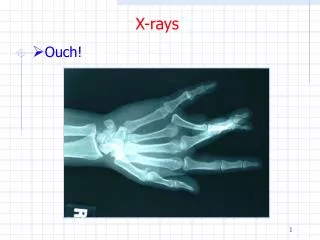
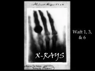
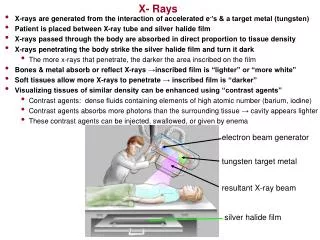
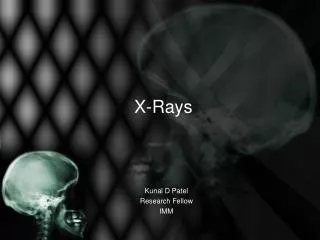
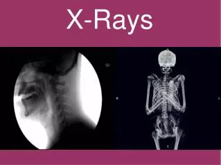
A New Kind of Rays • Wilhelm Conrad Röntgen • German physicist who produced and detected Röntgen rays, or X-rays, in 1895. • He determined that these rays were invisible, traveled in a straight line, and affected photographic film like visible light, but they were much more penetrating.
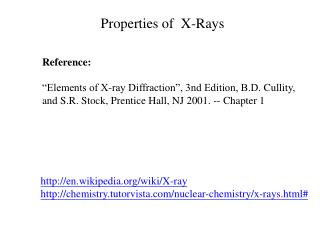
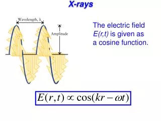
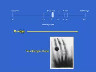
Properties of X-Rays • Electromagnetic radiation (l = 0.01 nm – 10 nm) • Wavelengths typical for XRD applications: 0.05 nm to 0.25 nm or 0.5 to 2.5 Å • 1 nm = 10-9 meters = 10 Å • E = ħc / l
Generation of Bremsstrahlung Radiation • “Braking” radiation. • Electron deceleration releases radiation across a spectrum of wavelengths. Electron (slowed down and changed direction) nucleus Fast incident electron electrons X-ray Atom of the anode material
Generation of Characteristic Radiation Emission • Incoming electron knocks out an electron from the inner shell of an atom. • Designation K,L,M correspond to shells with a different principal quantum number. Photoelectron K M L K Electron L K
Generation of Characteristic Radiation • Not every electron in each of these shells has the same energy. The shells must be further divided. • K-shell vacancy can be filled by electrons from 2 orbitals in the L shell, for example. • The electron transmission and the characteristic radiation emitted is given a further numerical subscript. Bohr`s model
Generation of Characteristic Radiation Energy levels (schematic) of the electrons M Intensity ratios KKK000 L K K K K K
Emission Spectrum of an X-Ray Tube:Close-up of Ka Cullity, B.D. and Stock, S.R., 2001, Elements of X-Ray Diffraction, 3rd Ed., Addison-Wesley
Sealed X-ray Tube Cross Section • Sealed tube • Cathode / Anode Cullity, B.D. and Stock, S.R., 2001, Elements of X-Ray Diffraction, 3rd Ed., Addison-Wesley • Beryllium windows • Water cooled
Modern Sealed X-ray Tube • Tube made from ceramic • Beryllium window is visible. • Anode type and focus type are labeled.
Sealed X-ray Tube Focus Types: Line and Point Target Take-off angle • The X-ray beam’s cross section at a small take-off angle can be a line shape or a spot, depending on the tube’s orientation. • The take-off angle is the target-to-beam angle, and the best choice in terms of shape and intensity is usually ~6°. • A focal spot size of 0.4 × 12 mm: 0.04 × 12 mm (line) 0.4 × 1.2 mm (spot) Filament Spot Target Line
Interactions with Matter d incoherent scattering Co (Compton-Scattering) coherent scattering Pr (Bragg-scattering) wavelengthPr absorption Beer´s law I = I0*e-µd intensity Io fluorescence > Pr photoelectrons
Coherent Scattering • Incoming X-rays are electromagnetic waves that exert a force on atomic electrons. • The electrons will begin to oscillate at the same frequency and emit radiation in all directions. e-
Coherent Scattering by an Atom • Coherent scattering by an atom is the sum of this scattering by all of the electrons. • Electrons are at different positions in space, so coherent scattering from each generally has different phase relationships. • At higher scattering angles, the sum of the coherent scattering is less. 2q
Atomic Scattering Factor • Scattering factor is used as an indication of the strength of scattering of an atom in particular direction. • Scattering is a maximum in the forward scattering direction and decreases with scattering angle. f= Amplitude of wave scattered by atom Amplitude of wave scattered by one electron
Diffraction of X-rays by Crystals • The science of X-ray crystallography originated in 1912 with the discovery by Max von Laue that crystals diffract X-rays. • Von Laue was a German physicist who won the Nobel Prize in Physics in 1914 for his discovery of the diffraction of X-rays by crystals. Max Theodor Felix von Laue (1879 – 1960)
X-ray Diffraction Pattern from a Single-crystal Sample Rotation Photograph
Diffraction of X-rays by Crystals After Von Laue's pioneering research, the field developed rapidly, most notably by physicists William Lawrence Bragg and his father William Henry Bragg. In 1912-1913, the younger Bragg developed Bragg's law, which connects the observed scattering with reflections from evenly-spaced planes within the crystal. William Henry Bragg William Lawrence Bragg
Bragg’s Law • X-rays scattering coherently from 2 of the parallel planes separated by a distance d. • Incident angle and reflected (diffracted angle) are given by q.
Bragg’s Law • The condition for constructive interference is that the path difference leads to an integer number of wavelengths. • Bragg condition concerted constructive interference from periodically-arranged scatterers. • This occurs ONLY for a very specific geometric condition.
Bragg’s Law We can think of diffraction as reflection at sets of planes running through the crystal. Only at certain angles 2θare the waves diffracted from different planes a whole number of wavelengths apart (i.e., in phase). At other angles, the waves reflected from different planes are out of phase and cancel one another out. n = 2d sin() d
Reflection Indices z • These planes must intersect the cell edges rationally, otherwise the diffraction from the different unit cells would interfere destructively. • We can index them by the number of times h, k and l that they cut each edge. • The same h, k and l values are used to index the X-ray reflections from the planes. y x Planes 3 -1 2 (or -3 1 -2)
c b a Examples of Diffracting Planes and their Miller Indices • Method for identifying diffracting planes in a crystal system. • A plane is identified by indices (hkl) called Miller indices, that are the reciprocals of the fractional intercepts that the plane makes with the crystallographic axes (abc).
Diffraction Patterns Two successive CCD detector images with a crystal rotation of one degree per image: For each X-ray reflection (black dot), indices h,k,lcan be assigned and an intensity I = F 2 measured
Reciprocal Space • The immediate result of the X-ray diffraction experiment is a list of X-ray reflections hkl and their intensities I. • We can arrange the reflections on a 3D grid based on their h, k and lvalues. The smallest repeat unit of this reciprocal lattice is known as the reciprocal unit cell; the lengths of the edges of this cell are inversely related to the dimensions of the real-space unit cell. • This concept is known as reciprocal space; it emphasizes the inverse relationship between the diffracted intensities and real space.
The Crystallographic Phase Problem • In order to calculate an electron density map, we require both the intensities I= F 2 and the phases aof the reflections hkl. • The information content of the phases is appreciably greater than that of the intensities. • Unfortunately, it is almost impossible to measure the phases experimentally! This is known as the crystallographic phase problem and would appear to be unsolvable!
Crystal Structure Solution by Direct Methods Early crystal structures were limited to small, centro-symmetric structures with ‘heavy’ atoms. These were solved by a vector (Patterson) method. The development of ‘direct methods’ of phase determination made it possible to solve non-centro-symmetric structures on ‘light atom’ compounds
Rapid Growth in Number of Structures in Cambridge Structural Database
The Structure Factor F and Electron Density ∫ Fhkl = Vxyz exp[+2i(hx+ky+lz)]dV xyz = (1/V) hklFhkl exp[-2i(hx+ky+lz)] Fand are inversely related by these Fourier transformations. Note that is real and positive, but F is a complex number:in order to calculate the electron density from the diffracted intensities I = F2, we need the PHASE () of F. Unfortunately, it is almost impossible to measure directly!
Real Space and Reciprocal Space Real Space • Unit Cell (a, b, c, , , ) • Electron Density, (x, y, z) • Atomic Coordinates –x, y, z • Thermal Parameters – Bij • Bond Lengths (A) • Bond Angles (°) • Crystal Faces Reciprocal Space • Diffraction Pattern • Reflections • Integrated Intensities – I(h,k,l) • Structure Factors – F(h,k,l) • Phase – (h,k,l)
X-Ray Diffraction X-ray beam 1Å (0.1 nm) ~ (0.2mm)3 crystal ~1013 unit cells,each ~ (100Å)3 Diffraction pattern on a CCD detector