D-Type Flip-Flops in Sequential Logic Circuits
120 likes | 149 Vues
Learn about D-FF, SR Latch, clock synchronization, NAND gates, memory, feedback mechanisms, and more in the realm of sequential logic circuits.

D-Type Flip-Flops in Sequential Logic Circuits
E N D
Presentation Transcript
Lab 8. D-type Flip-Flop Presenter: Chun-Hsien Ko Contributors: Chung-Ting Jiang and Lin-Kai Chiu Dept. of Electrical and Computer Eng., NCTU
Sequential Logic Circuits • Status (Memory) and Timing (Clock) • How to Save the Status? • Latch, e.g., SR Latch • Flip-Flop, e.g., D-FF (D-type Flip-Flop) • LAB: • IC:7400 (NAND) x 2、LED x 1 Dept. of Electrical and Computer Eng., NCTU
Two Types of Logic Circuits • Combinational logic circuits • depends only on current inputs • E.g., A + B = C • Sequential logic circuits • depends on past and current inputs • E.g., A[n]=A[n-1]+B Memory and Clock!! Dept. of Electrical and Computer Eng., NCTU
SR Latch • Steady state results • Feedback from output 0 1 0 1 R R R R 1 Q Q Q Q 0 1 Q’ Q’ Q’ Q’ S S S S 0 Q 1 Q’ 1 Dept. of Electrical and Computer Eng., NCTU
SR Latch • Steady state results • Feedback from output (2) (1) 1 0 1 (3) 1 0 0 (4) 1 (4) 0 R R R R 1 Q Q Q Q 0 1 (3) (1) A NAND 1 = A’ 1 Q’ Q’ 1 Q’ Q’ S S S S (2) 0 (4) (1) 1/0 0/1 Q 1 (3) (2) 0/1 1/0 Q’ 1 Dept. of Electrical and Computer Eng., NCTU
Timing: Clock Input • When to set and reset • How to synchronize devices with memory • Positive (rising) edge triggered • Negative (falling) edge triggered time Dept. of Electrical and Computer Eng., NCTU
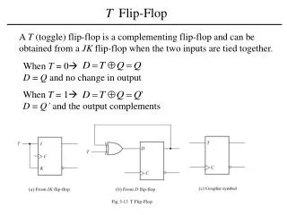
Flip Flops • Using clock input to determine the status changing • Different types of Flip-Flop • SR (Set and Reset) • D (Input = Output), T (Input != Output) • JK (When S=0, R=0, Q=Q’) • Trigger type • Rising(positive)-edge • Falling(negative)-edge Dept. of Electrical and Computer Eng., NCTU
LAB 8: Implement a D-FF with NAND gates • Goal: D-type positive edge triggered Flip-Flop • IC: 7400 (NAND) x 2、LED x 1 Dept. of Electrical and Computer Eng., NCTU
CLK: 0->1, S = D, R = D’; otherwise, R=1, S=1 1 R 2 5 Q Clock 6 Q’ 3 S SR Latch 4 D Dept. of Electrical and Computer Eng., NCTU
Clock: 0->1 Clock = 1, D: X->X’ Clock = 0 X X->X X X’ 1 1->X’ R R R 0->1 1 0 Clock Clock 1->X Clock X 1 S S S X’ X’->1 X’ X X X->X’ D D D S, R will not change with D S = X, R = X’ ⟹ Set the latch as X S, R = 1 ⟹ Hold Dept. of Electrical and Computer Eng., NCTU
How to implement 3-input NAND gate? 1 R 2 5 Q Clock 6 Q’ 3 3 S 4 D How to realize 3-inputs NANDs with 2-inputs NANDs? Dept. of Electrical and Computer Eng., NCTU
You can connect output of 555 to a buffer • Oscillator would be more stable • E.g., connect output of 555 to an inverter or AND output of 555 with signal 1 + - 555 Calculator (Website) Dept. of Electrical and Computer Eng., NCTU