Advanced Kicker Designs for Head-on Collision Beams at 250 GeV: RF and Magnetic Innovations
This paper discusses advanced kicker systems designed for head-on collisions in particle accelerators, specifically at 250 GeV. The focus is on optimizing the magnetic field strength and improving shielding techniques. Key specifications include a magnetic strength of approximately 1 T over 4 km, with studies revealing the importance of component separation and RF waveform designs. Emphasis is placed on using magnetic alloys like Finemet for efficiency, exploring configurations that reduce core loss, and suggesting upgrades for future 1 TeV operations. This research supports the ongoing advancements in beam manipulation technologies.

Advanced Kicker Designs for Head-on Collision Beams at 250 GeV: RF and Magnetic Innovations
E N D
Presentation Transcript
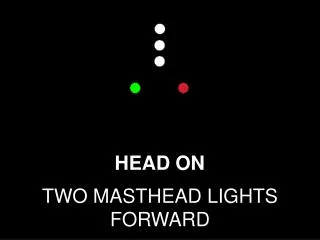
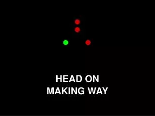
RF Kicker for Head-on-Collision • Y. IwashitaAccelerator Laboratory, • Advanced Research Center of Beam Science, Institute for Chemical Research, Kyoto University, Gokanosho, Uji, Kyoto 611-0011, JAPANiwashita@kyticr.kuicr.kyoto-u.ac.jphttp://wwwal.kuicr.kyoto-u.ac.jp
Magnetic Field Strength B = ~1 T.km @ 250GeV =L(4m)/(1mrad)=4km B=0.25T
Variant Better shielding Step at center? Sketch of a Kicker DC+3MHz (+9MHz) L=4m Stored Energy W ~ 125[J] @0.25T 3cm x133 units
Magnetic Alloy (Finemet) Large Test Core for JPARC Q <1 for non-cut core Q~10 for cut core @a few mm gap
FT-3L High B, low core loss, high Tc
Core Loss FT-3L is the best option here.
Single RF needs DC Wide Base needs DC Two RF in One No DC Narrow Base Two RF in One Waveforms-1 Two RF in One: Two cosine components superposition
No DC Separate RF Short LRF Two RF No DC Separate RF 6MHz too (if 2 sides OK) Short LRF Two RF Waveforms-2 Separate RF: Each component for each separate kicker
Separate two RF system for the latter two options. Phase slip for in-bunch can be compensated by phasing. ––> less perturbation Combination
MA has been used for RF accelerating cavity to generate high voltage(V==BS). –> Not for generation of B. ( R&D! ) The number units 133 reduces a serious hazard. (133 cores, 133 Amp’s) Upgradable to 1TeV(6MHz) –– Two sets? Easier than Crab-cavity Comments