Download

1 / 49
490 likes | 635 Vues
ANDE Status Report 26APR2004. Team Leader: Benjamin Aaron Comms: Ernesto Villalba Power: Crispina Weissenberg. Presentation Outline. ANDE NRL Background USNA Specific Background Engineering Progress Review Demonstration. NRL Mission Objectives. Primary

E N D
ANDE Status Report26APR2004 • Team Leader: Benjamin Aaron • Comms: Ernesto Villalba • Power: Crispina Weissenberg
Presentation Outline • ANDE NRL Background • USNA Specific Background • Engineering Progress Review • Demonstration
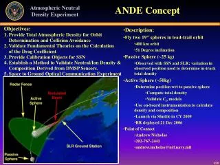
NRL Mission Objectives • Primary • To provide total atmospheric density for orbit determination and collision avoidance. • Secondary • To demonstrate space-to-ground optical communications through the use of Modulating Retro-Reflectors (MRRs). • To validate fundamental theories on the calculation of the drag coefficient. • To establish a method to validate Neutral Density and Composition derived from Defense Meteorological Satellite Program (DMSP) sensors.
NRL Concept • The ANDE project will use two spherical satellites to determine the Earth’s atmospheric density. • A passive sphere, ANDE I, which would have no payload, would be populated with optical retro-reflectors to be sighted by satellite laser ranging facilities • An active sphere, ANDE II, would similarly be sited by laser ranging sites, but would send down data. • As we can achieve the primary objective with any number of passive spheres, more focus has been given to the structure and manufacture of ANDE II. • Our goal was to provide the communications and power package for ANDE II.
ANDE History • ANDE MOA signed 12/2001 • ANDE SRR 9/2002 • ANDE PDR 10/2002 • ANDE CDR 11/2002 • USNA ANDE Progress Review 4/26/2004
Mechanical Requirements • ANDE sphere must be • 19” diameter sphere • Area must be constant to within 0.1% from any orientation • Mass must be known to 0.5 % • Surface roughness maximum gap of 0.5 mm • Meet environmental specifications for Shuttle launch • Retro Locations (Quantity 30) • Accurate to ±0.5º combined azimuth, elevation tip & tilt to normal. • CG located at center of sphere • Venting requirement for change in pressure from launch to space • Provide two lift points for transport • No mechanical/electrical interface to the launcher • Battery access for replacement
Instrument Requirements • Transmit (PV current and sphere temp ) every 1 minute • RF communications system from USNA • RF Inhibits (Separation Switches) • Magnetic switch (at each pole along ejection axis) • No external antenna • Photovoltaics (quantity 6) • Distributed at the end points of three nearly orthogonal axes • Monitor current • Laser Diodes (quantity 6) • Distributed at the end points of three nearly orthogonal axes • 6 unique pulse rates that can be resolved at Maui • Duty cycle, only on over when elevation to Maui >20º
External Component Layout • Corner Reflector (30) • Photovoltaic (6) • Laser Diode (6) • GSE Interface (1) • RF Inhibit (2) • Ejection axis • Lift Point (2)
Insert Mounting System • Aluminum 6061-T6 • Threaded Insert • 1.17 in. diameter • 32 threads per inch • Internal driven by specific component • Venting holes on some inserts (LD, LP) • Retro mount shown
Preliminary Payload Enclosure • Aluminum 6061-T6 • 10.5” x 7.5” x 4” • One Enclosure per Hemisphere • Enclosures (2) • Battery Banks (2) • Communications (1)
CAPE Ejection System • Canister for All Payload Ejection (CAPE) • Will be deployed from Space Shuttle • Designed to fit payload requirements for Space Shuttle.
CONOPS • US Space Surveillance Network (SSN) will track the two satellites after orbit insertion and provide accurate orbital state vectors • Satellite Laser Ranging (SLR) sites, both domestic and international, acquire the spacecraft and make routine SLR observations • Access for the Maui site • Elevation angle constraints 20° < elev < 85° • Night observations • Beginning of Life: alt = 400 km access = 3-4 minutes • End of SLR tracking life: alt = 300 km, access = 2-3 minutes • Activate Laser Diodes via amateur radio uplink over Maui for spin orientation determination. Laser diodes on timer circuit to conserve power • USNA has a collaborating amateur ground station to control ANDE and activate laser diodes locally in Maui • ANDE Data downlinked • Temperature data. • Photovoltaic current & voltage data
USNA Mission Statement • To construct a communications system able to transmit telemetry data and provide communications support in the amateur satellite service, for at least one year, via a zero drag antenna for the ANDE risk reduction flight satellite.
USNA Mission Requirements • 1. Mechanical Configuration (Spherical) • 2. Transmit Telemetry Data • 3. Command and Control • 4. Communications Transponder in Amateur Satellite Service • 5. Power System
USNA Spring 2004 Schedule DateEvent JAN 06 New team member selection and orientation COMPLETE JAN 30 Mechanical Review with NRL COMPLETE MAR 26 Complete Prototype and Testing COMPLETE APR 2 Complete Lithium Battery Vacuum Testing COMPLETE APR 14 Begin Flight Battery Board Assembly IN WORK APR 26 System Progress Report Presentation IN WORK APR 28 Begin Flight Board Assembly APR 30 Test Operations To be completed by MAY 2004: Complete and Deliver Hardware to NRL
USNA PerformanceCriteria • Ideal Performance of ANDE (100%): • Temperature telemetry data transmitted by ANDE and received by ground station • Ensure that Lasers are powered for spin rate determination • User communications able to fulfill amateur radio communications status • Above criterion fully functional for expected life of ANDE (1 year)
Mission Architecture • Maui Laser Ranging Station – Tracking • USNA – Command and Control • NRL – Data Reduction/Analysis • Amateur Ground Stations (Users) – Global Telemetry Reception and Communications Experiment
ANDE Block Diagram • 2 hemispheres, identical except for their sleep timers • primary is on a 15/1.5 sec cycle • secondary is on a 40/1.5 sec cycle • 7 sensors on the surface of each hemisphere • 3 photovoltaic cells combined with 3 thermistors • 1 thermistor with the corner reflector • 4 lines of data from the cross connect, 1 from the batteries, 8 internal to the TNC • The multiplexer condenses these to 5 channels requiring 4 transmissions for one complete set of data • The batteries provide power to the multiplexer, sleep timers, TNC, RX, TX and lasers
ANDE Telemetry Channels • This diagram displays what pieces of data are being displayed on all 20 telemetry channels: • Voltages from the 3 photovoltaic cells • Current from all 4 battery packs • Temperatures of the photovoltaic cells, a battery pack, one laser and one corner reflector • The other telemetry data is internal to the TNC
ANDE Sensors • This diagram better displays the 7 sensors inserted in the mounting system distributed throughout the surface of the sphere. • With each photovoltaic cell there will be a thermister • One thermister with a corner reflector • Thermisters on each of the 4 battery packs
Basic Cross Section of ANDE Laser circuitry
VHF Transmitter • Off the shelf • Simple without microprocessor circuits (less vulnerable to SEUs) • Used on PCSAT, PCSAT2 and Sapphire
VHF Receiver • Off the shelf • Simple without microprocessor circuits (less vulnerable to SEUs) • Used on PCSAT, PCSAT2 and Sapphire • The volume and squelch controls will be removed for flight
Terminal Node Controller • Provides Telemetry, Command and Control • Similar to an External Modem • Off the shelf • Used on PCSAT, PCSAT2 and Sapphire
Interface Board Layout • Tested each component after placing on board. • Construction Order and Testing • Power Distribution • Telemetry Multiplexer • Telemetry Equations • Battery Switching • Current Sensors • Sleep/Wake Timer • Runtime Counter
Interface PCB • Red – Top of Board • Green – Bottom of Board • Yellow – Component Layout • Engineering Model is Fully Tested • Ready to Order Flight Board from ExpressPCB.com
Spherical Antenna that transmits and receives at 145.825 MHz T/R switch controls the transmitting and receiving functions Two Communications Trays, primary and secondary System asleep 90 % of the time Communications Block Diagram
FCC Licensing and ITU Requirements • Requirements • Plain Language • General Communications Support (Transponder) • Open System for Educational Purposes • Published Protocols • Status • International Amateur Radio Union (IARU) Request Submitted • FCC 5 Month Advanced Notice is required
ANDE Link Budget • Downlink • EIRP = 33 dBm (2W) • Space Loss = -146 dB @ 2000 mi. • Receiver Threshold = -117 dBm • Margin = 4 dB • Uplink • EIRP = 35 dBm (3W) • Space Loss = -146 dB @ 2000 mi. • Receiver Threshold = -117 dBm • Margin = 6 dB
Antenna Design • Top and Side view of insulator between hemispheres. Lets us use ANDE as a folded dipole antenna. This allows one side to be shorted • A-side and B-side are “phased” together to share one antenna • Circuit provides T/R switching
Telemetry • 20 Telemetry Channels • 3 Multiplexer Chips • 4 packets with 5 channels of telemetry transmitted serially • Run timer/counter keeps track of system usage • Each telemetry channel has unique voltage divider to scale into 0-5 volt range of A/D converter
Telemetry Equations • Conditioning of Telemetry Equations • Derive values from telemetry count • Voltage dividers were selected to make simple telemetry equations
ANDE Power Budget Total = 35 mA
Power System • Battery Selection • Tadiran TL-5930 D-size Lithium Thionyl Chloride (Li/SOCl2) primary • 19 Ah capacity • 5 ma nominal discharge • Rated temperature range –55 to +85C • Designed for harsh environments • Bobbin construction • Safety Requirement
Battery Life Management • Batteries have a flat discharge curve. Telemetry says nothing about remaining battery capacity • Separately use one battery pack at a time until exhaustion • Biggest loads are lasers and transmitters, switch them to each battery pack in turn • All 4 battery packs contribute in parallel to power TNC and Receiver
ANDE Battery Safety Issues and Tests • Lithium primary cells are an explosive hazard when current is reversed in power system. • All Batteries were subject to up to 3A reverse current and none failed (no explosions) • Battery Leakage Tests • Batteries placed in a vacuum chamber for 24 hours at 25°C and 85°C. No leakage occurred
Battery Board Schematic • 2 diodes per battery provide double fault tolerance for reverse current. • Safety fuses are in the ground leg of the circuit because current would flow in that direction if the batteries shorted to the case.
Wiring Harness • Very Complex • Design Criteria: • Different Connector Sizes • Different Sex Connections • Batteries Connected With Female Connections • #22 Wire Site Up To 5A
Parts Status • Piece Parts • 81.05% From Stock • 18.95% From DIGI-KEY • Current Sensors Back Ordered • Modules • Express PCB (Ready to Order Flight Board) • Tadiran Lithium Batteries (We have flight batteries) • TNC from Kantronics • Custom Firmware Defaults
ANDE Auxiliary Serial Port Experiment • ANDE has a similar transponder to PCSAT1 and 2 • Transponder has a general purpose serial port for auxiliary experiment • ANDE uses a voice synthesizer that can speak messages
Engineering Model Testing • Remote System Operation (SYSOP) • Password Challenge and Response • Battery Selection System • Battery Life Management • Laser Control • Telemetry Sensors • Telemetry Equations • Calibrated GSE Software
USNA Semester Accomplishments • Battery Leakage Testing • Built Engineering Model • Test Operations • Began Flight Assembly (Battery Board and Interface Board) • Goal is to complete ANDE Communications and Power components for spacecraft this semester
Demonstration of Engineering Model • Engineering Model • Ground Station • Walkie-Talkie (users on USNA sailboat) • Turn ANDE on • Observe meter current • Observe sleep/wake timer circuit
Engineering Model Demo telemetry commands user comms voice comms Msgs position ANDE Engineering model Sailboat user radio Gnd Stn laptop
Demonstration Sequence • Use ping commands to wake ANDE • Observe 40 seconds of telemetry • Prove sensors work • Send communications to walkie-talkie • Log on • Go through sequence of battery boards • Turn on the LEDs • Observe temperature rise on lasers • Set LEDs off and observe telemetry response • Log off • Fail each battery