Download
1 / 22
220 likes | 346 Vues
Y. Ohnishi KEK Snowmass2001. Luminosity of 10 35 cm -2 s -1 at KEKB. Preliminary plan Machine parameters RF system Vacuum system Injector. Preliminary Plan. Luminosity of 4.49x10 33 cm -2 s -1 was achieved at KEKB.

E N D
Y. Ohnishi KEK Snowmass2001 Luminosity of 1035 cm-2s-1at KEKB Preliminary plan Machine parameters RF system Vacuum system Injector
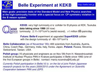
Preliminary Plan • Luminosity of 4.49x1033 cm-2s-1 was achieved at KEKB. • Major target of B physics is CP violation, especially sin21(or sin2b): • Belle/KEKB : 0.58±0.33 (10.5 fb-1), March 2001. • Int. luminosity from KEKB is 30 fb-1 now. Statistical error will be 0.19. • There is a chance to say 3 S.D. significance this summer(?). • Integrated luminosity of100 fb-1 is needed to achieve the required accuracy of 0.1 for sin21. • We expect to reach 100 fb-1 within 1.5 year even if the luminosity is still 4x1033 cm-2s-1. (very conservative) • BTeVandLHC-B will become strong competitors in 5 years.
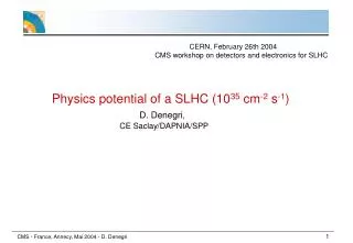
Preliminary Plan (cont’d) • KEKB will loose its competitiveness in 2005-2007. • Luminosity of BTeV or LHC-B corresponds to 1035 cm-2s-1 e+e- collider. • SUSY related B physics at 1035 cm-2s-1 e+e- collider is a very attractive choice. • We hope to upgrade KEKB to Super KEKB(1035 cm-2s-1 ) during 2004-2005 and begin physics run in 2006. • We try to improve luminosity to 1034 cm-2s-1 up to 2004. • KEKB is R&D machine for Super KEKB. • Super KEKB project consists of theorists/experimentalists/accelerator staffs of universities and KEK. (18/5/30) • We will submit LoI to HEP community and KEK in winter 2001
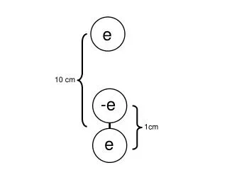
Parameters for Super KEKB(1035 cm-2s-1) • Luminosity formula: • Beam-beam tune shift parameters: • Assumed that the “transparency” conditions: • Alternative expression for luminosity:
Parameters for Super KEKB (cont’d) • Design luminosity of KEKB is 1034 cm-2s-1. • To achieve 1035 cm-2s-1: Squeeze beta at IP. : y* sz 3 mm (coherent radiation?) Higher beam current : 10 A for LER and 3 A for HER
Coherent Synchrotron Radiation • Power of coherent synchrotron radiation (Kheifets,Zotter) Particles: Gaussian distribution N: particles/bunch r: bending radius h: height of chamber • incoherent • E ∝√NP ∝N z • coherent • E ∝NP ∝N2 coherent condition z≦l z
Coherent Synchrotron Radiation(cont’d) • The ratio of coherent power to incoherent: LER: 3.5 GeV Bending radius: = 16.3 m Chamber height: h=47mm Coherent radiation can be ignore for 3mm bunch length (?)
Questions • Beam current is 10x3 A. • Beta(y) at I.P = 3 mm • Bunch length = 3mm • Energy(or Particle) exchange: • 3.5 GeV e+/8 GeV e-to 3.5 GeV e-/8 GeV e+ • Advantage: • Beam blow-up due to photoelectron cloud(?) If fast ion instability for electron beam is ok. • Injection (injection rate: e- > e+ at KEKB). • Once machine parameters are fixed, questions are: • RF system ? • Vacuum system ? • IR design ? • Injector ?
Layout of KEKB (not Super KEKB) Double ring, Asymmetric collider Circumference: 3km
RF System • Beam current at Super KEKB is 3 times larger than KEKB. • Number of bunches is 15000 or 5120 ? • If we choose harmonic number of15000, we have to develop completely new 1.5 GHz RF system. (Current RF frequency is 508 MHz.) • We consider RF frequency is 508 MHz to minimize the cost, time, and man power. • Normal conducting cavities (ARES) for LER and normal+superconducting cavities(SCC) for HER. • The severe requirement on HOM damping. • Rf system for LER depends on whether wiggler exists or not.
RF System (cont’d) • RF parameters (RF unit includes klystron, power supply, wave guide, circulator, dummy load, cooling, etc)
RF System (cont’d) • RF system needs small modifications if we keep 508 MHz RF frequency used at KEKB. • However, we have to develop new HOM damper for higher beam current. • We increase NC(ARES) cavities from 32 to 36 and SC cavities from 8 to 12. • We should have 36 NC(ARES) cavities for KEKB, we only add 4 SCC. • Klystron for Two NC(ARES) cavities is modified to Klystron for one NC(ARES) cavity. Number of RF units becomes twice of KEKB. • We consider RF system with wiggler for LER at this stage.
Vacuum System • Parameters of vacuum system Max. cooling power is 〜8 MW. New powerful cooling system has to be built. This issue is for institute not for accelerator division. It is difficult for copper chamber. 510 A/m 130 A/m 200 kV/m These values are tested and confirmed.
Vacuum System (cont’d) • Ante-chamber for positron ring: In the case of energy exchange We have no experience even if GlidCop is used. R&D for material. Make incident angle slant? practicable
Vacuum System (cont’d) • Movable masks. • Photo shows the early version of movable mask. • SiC blocks were equipped as a HOM absorber, since trapped mode was very serious. • However, beam current was limited by the absorbed power(estimated to be 500W). • This kind of mask can not be used for huge beam current machine. • The most serious problem is damage of mask head. • R&D for the structure and material is needed.
Vacuum System (cont’d) • Latest version of movable mask at KEKB(LER). • Movable chamber. The chamber works as a mask. • There is no trapped mode. • We have already observed mask damage(looks like previous photo). • To avoid mask damage, mask should be hybrid structure of Al and copper.(Just make energy loss point at mask)
Positron Beam Blow-up • Positron beam blow-up caused by photoelectrons is reduced by solenoid field. Spec. Luminosity/bunch Beam size measurement using SR interferometer. All solenoid on Partial solenoid off All solenoid off
Positron Beam Blow-up (cont’d) • Solenoid coils are also necessary for Super KEKB. • Chambers in positron ring are wrapped by solenoids: • Straight section as well as bending section. • Bellows, inside of steering magnets, …
Injector • Short lifetime due to collision: 10A/100 min=1.7 mA/s. • Powerful injector is needed to keep the rings filled up. • Super KEKB will be very inefficient machine. KEKB(current status:4.3x1033) 3mA/s(e-)/1.5mA/s(e+) 800mA(HER)/900mA(LER) High efficiency! Top-up Inj.+dead time=6.5min Luminosity efficiency Super KEKB(upgrade injector) 15mA/s(e-)/3mA/s(e+) 3A(HER)/10A(LER) Inj.+dead time=12.8min Super KEKB 3mA/s(e-)/1.5mA/s(e+) 3A(HER)/10A(LER) Inj.+dead time=50min
Injector (cont’d) • Improvement of Injection rate: • Charge intensity can be increased from 1nC to 5 nC for electron. • Positron charge becomes twice, if two-bunch acceleration is performed. We have already tested. • Energy exchange(3.5 GeV e-/8GeV e+) may help beam blow-up due to photoelectron cloud in positron ring. • To accelerate positron up to 8 GeV, there are two possibilities: • Improvement of accelerating electric field(simple): • C-band is a candidate instead of S-band. • One of techniques of Japan Linear Collider. • Recirculation(S-band) with damping ring(similar to SLC): • In order to do recirculation, next RF pulse is used. • Damping ring is needed so that beams wait for next RF pulse. • Beam transport lines are very complicated.
S-Band Injector (cont’d) Layout of injector for KEKB 10nC e- for e+ production 1 nC e- for injection B A Gun J-Arc 1.7 GeV KEKB e+ 3.5 GeV C 1 2 3 4 5 ECS e+ Target e- 3.7 GeV KEKB e- 8 GeV Layout of injector for super KEKB Preliminary plan S-Band B A Gun C-Band 40 MeV/m J-Arc 1.7 GeV 1.1x2 + 2.2x3 = Max 8.8 GeV Super KEKB e+ 8 GeV C 1 2 3 4 5 ECS e+ Target e- 3.9 GeV Super KEKB e-3.5 GeV
Summary • Machine parameters of Super KEKB: • Beam current: 10A(3GeV e-)/3A(8GeV e+) • Beta at I.P: by*=3mm • Bunch length: sz=3mm • Number of bunches: 5120 • Crossing angle at I.P: 15 mrad(?) • RF system is not so difficult (practicable). • Development of HOM damper • Vacuum system is very difficult. • R&D of materials and structure of vacuum chamber • Injector will be widely modified to exchange energy and improve beam intensity. • C-band or recirculation • Two-bunch acceleration