Download
1 / 25
250 likes | 280 Vues
This study delves into the complications of assessing consequences following a fire and explosion involving a multicomponent mixture of unknown composition. The method of thermodynamic substitute is applied to evaluate the hazards and impacts in such scenarios.

E N D
Some problems in an assessment of the consequences of a fire and an explosion during the multicomponent mixture unknown composition release.Melania Pofit-SzczepańskaThe Main School of Fire Service, Firefighting and Rescue Operation Department Słowackiego Street 52/5401-629 Warsaw, Poland
Consequences of hazardous substances releases The important part of the safety report is the analytical part in which fire, explosion andtoxicity hazards are analyzed as well as the consequences of these releases to the atmosphere. If the released medium is the substance of a known composition and the parameters of process are known too, the calculation of the consequences of these releases is not difficult. The descriptions of the way of procedure can be found in the literature. If however, the mixture of unknown composition leaks through the rupture of the pipeline or vessel the assessment of the consequences of these releases is more complicated.
The method of thermodynamic substitute The methodhas been applied to the assessment of fire and explosion consequences during the rupture of the pipeline and the release of the slops mixture of unknown composition to the atmosphere in a Polish refinery.This method called “the method of thermodynamic substitute”, is one of the methods used in the calculations different parameters dealing with release of dangerous substances.
The method of thermodynamic substitute The single component as a thermodynamic substitute is used very often. Of course, the most reliable use of a single component consequence model results when the single component simulates the behaviour of the multicomponent fluid over all potential conditions from storage conditions to ambient atmospheric conditions. Naturally, this involves an intimate knowledge of the thermodynamic behaviour of the mixture.
Single component model The single component models are used very often because they are much easier and generally run faster. Considering D.W. Johnson’s example : the release of methane – pentane vapour from a large vessel operating at 3 bars and 65oC and a release of pure propane in the same conditions. The release will escape through a 15 cm diameter hole made at the side of the vessel. The release is angled 45o above horizontal. The release rate will be relatively constant since pressure and temperature in the large vessel will change slowly with time. In table 1 the computed results are given and fig. 1 shows the LFL contours. With many uncertainties the agreement is good. Thus it appears possible to model release.
Item Propane C1-C5 Vapour production [kg/s] 15,7 15,8 Height above Grade [m] 90 75 60 45 30 15 0 Distance to LFL [m] 30 30 Height above grade at LFL [m] 30 30 - 15 0 15 30 45 60 75 90 105 120 Downwind Distance [m] Fig. 1 Dispersion of vapour releases to the lower flammable limit Table 1.
road 1 road A 3 2 1 Fig. 2 The arrangement of the installation and the location of vessels
Fig. 3 Visible damage on the pipeline which cause the realistic accidental spill
road 1 road A 3 2 1 Case study • Problem: • The refinery, division-slops installation. An arrangement of the installation and the cylindrical vessels 1, 2, 3 of a division are shown in thefig 2. The road A, road 1and cross-road A1 can be seen. Tank cars waiting for the loading of asphalt and their position when fire and explosion took place are markedin yellow. The area of an enveloped accident amounted to about 5000m2. The fill of vessels: 3 – 18%, 2 – 26%, 1 – 80%. • An assumed course of the incident: • At first it was a small leak through a small hole. It was a long time before the slops were released through 0.1m diameter hole in the following conditions: t = 50oC, p = 0.5 bar. The part of slops according to their density were absorbed by the concrete bottom of pipelines duct or by the thermo-isolation of pipelines. The lightest fraction mixed with air generatedthe cloud of slops. Can be assumed that the released quantity of slops was larger than150tons (calculations). Data published in a literature indicate that the generation of cloud during the realistic accidental spill is possible if the flow out is above 100kg of relative non-reactive fuel (hydrocarbons).
Case study The following conditions were in the time of accidental spill: • night, • F - Pasquille class, • T = - 2,7oC • Vv = 2 m/s. In these conditions, the direction of wind had less influence on the cloud propagation than the buoyant forces. The flammable cloud have encountered an ignition source probably somewhere in the vicinity of the tank car 1 /fig. 2/ in the form of low energy source /damaged electric installation of tank car 1/.In order to analyse the development of fire and explosion, two variants of the procedure have been discussed. In the basis on the information received from the rafinery was assumed that the released mixture had the C1 to C8 composition and components were in equivalent concentrations.
n-butane could be the substitute C1 to C5 of the fraction n-heksane could be the substitute C6 to C8 of the fraction /liquid fraction/ For C6 to C8 For C1 to C5 Case study from the following causes: • the relative density of n-heksane ≈ 3.0 • the relative density of released • liquid mixture ≈ 3.4 • Lower flammability limit • of n-heksane ≈ 1.52% • Lower flammability limit • for the mixrure ≈1.61% • the relative density of n-butane ≈ 2.0 • the relative density of released • gases mixture ≈ 1.68 • Lower flammability limit • of n-butane ≈ 2.21% • Lower flammability limit • for the mixrure ≈2.36%
road 1 road A 3 2 1 Case study Assumptions applied in calculations: - fuel-air mixture burns in the way that no damaging overpressure is generating /flash fire/ - generated explosion is the deflagration - dispersion of the released mixture occurs in two types of surroundings: a)in obstructed environment, the vapour cloud is located in space between dike area and vessels and between the vessels 3 and 2 and pipelines ducts /fig. 2/, where the ruptured pipeline /fig. 3/ was situated b) in open space – the flammable mixture covers the area about 5000m2: the area of pipelines duct – cross-road A1 – a space outside of the cross-road – the space round tank cars waiting for the loading of asphalt.
Case study The generated cloud was spreading down from SE direction to NW. - The area of the tank car was 162m2 (18m x 3m x 3.5m). • - The volume: 567m3. - The area of pipelines duct was about 460m2 (46m distance from the realistic accidental leak to cross-road marked A1/fig 2/. - The open area (non-built) of accident was 1500m2. In tables 2-7 can be seen some results of the calculations: anoverpressure, positive-phase duration of explosion and the energies of combustion at different
Case study Distances from accidental leak : 10m, 30m, 48m, 68m and 100mwere considered and they made calculations of the explosion parameters possible in the following places:- - 10m – the nearest distance from an accidental leak to the dike area - 30m – the distance from an accidental leak to the vessel 3 - 48m – distance from the accidental leak to the cross-road A1 - 68m – distance from the accidental leak to the place where probably the piloted ignition occurred • 100m – the distance from the accidental leak to the place faraway 30m outside of thecross-road A1 /near tank car 1/ /fig. 1/ On the basis of the technical documentation the mass of theaccidental leaks was determined: - 6,000 kg - 10,000 kg - 20,000 kg
EXPLOSION PARAMETERS OF RELEASED SLOPS IN A FUNCTION OF THE DISTANCE FROM AN ACCIDENTAL LEAK Table 2. N-butane – thermodynamic substitute, obstructed environment.
Table 3. N-hexane – thermodynamic substitute, obstructed environment.
Table 4. N-butane – thermodynamic substitute, open, non-built environment.
Table 5. N-hexane – thermodynamic substitute, open, non-built environment.
Table 6. Summary comparison some results of the calculations of the range cloud vapour explosion /ST – n-hexane/ Table 7. Summary comparison some results of the calculations of the range cloud vapour explosion /ST – n-butane/
The analysis of results In the basis of the technological data and the analysis of the run of fire which had taken place before the explosion, you can explain the relationship: “fire–explosion–consequences”. The fire of slops cloud have started at about two o’clock at night when the cloud hadalreadypropagated for about 70 m towards the three tank cars. About 2 min after firethe first explosion took place which almost completely damaged the vessel no.3filled only in 18 % /photo 1-2/.
Photo 1. Deformation of vessel no.3 after the explosion with the visible displacement Photo 2. Deformation of vessel no.3, visible detachment from the foundations as a result of an explosion
The analysis of results • The vessel no.2 /filled 26 %/ was damaged by the second explosion after 45s later /photo 3/. • Probably, this time was needed to form explosive mixture because the hydrocarbons have the narrow flammability limits /about 1–10%/. The vessel no.3filled with benzol recovery oil in 80 % was less damaged /photo 4/.
Photo 3. Deformation of vessel no.2, visible detachment from the foundations and displacement outside concrete wall Photo 4. Deformation of vessel no.1
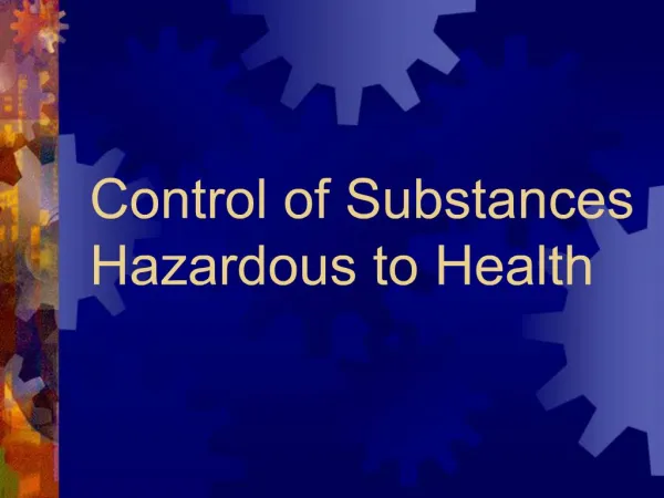
Conclusions • The safety reports and firefighting-rescue plans should contain: • characteristics of hazardous materials • indentification of the threat sources • the probable scenarios of the accidents • the quantitative evaluation of the potential results for both people and the environment • To calculate the results of the hazardous occurrences the knowledge of the input data is needed • Simulation via the use of pure component consequences makes it possible to predict more or less accurately conditions when a liquid or gases is released.