Biomedical Instrumentation I
Biomedical Instrumentation I. Chapter 7 Bioelectric Amplifiers from Introduction to Biomedical Equipment Technology By Joseph Carr and John Brown Part 2. Differential Amplifiers. R2. Infinite Input impedance thus current passes from R3 to R4 and from R1 to R2 . R1. -. E1. A. Vinput.

Biomedical Instrumentation I
E N D
Presentation Transcript
Biomedical Instrumentation I Chapter 7 Bioelectric Amplifiers from Introduction to Biomedical Equipment Technology By Joseph Carr and John Brown Part 2
Differential Amplifiers R2 • Infinite Input impedance thus current passes from R3 to R4 and from R1 to R2 R1 - E1 A Vinput R3 + Voutput E2 R4 Book Assumes: Vinput = E2-E1 And R1 =R3 and R2=R4 R1 R2 A E1 I1 I2 Voutput E2 A R4 R3 I4 I3
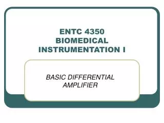
Advantages of Differential Amplifier • In differential mode you can cancel noise common to both input signals R2 1V R1 - E1 A 2V R3 + 3V Voutput E2 R4
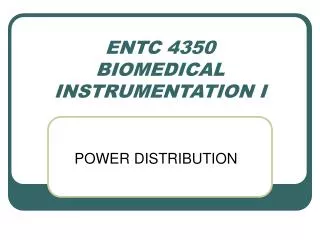
Instrumentation Amplifier E1 + R5 R4 • Give you high gain and high-input impedance. • Composed of 2 amplifiers in noninverting format and a 3rd amplifier as a differential amplifier - E1 - R2 + R1 Vinput Voutpt R3 R6 R7 E2 - + E2
Derivation of Gain for Instrumentation Amplifier step 1 E1 R1 I1 R3 E3 I2 E2 - + E2 R1 R3 E3 E1 E2 I1 I2
Derivation of Gain for Instrumentation Amplifier step 2 E1 + E4 - E1 R2 I2 I1 R1 E2 R1 R2 E1 E2 E4 I1 I2
R5 R4 E4 I5 - I4 + I6 Voutput I7 E3 R6 R7 Book Assumes R4 =R6 and R5=R7 R4 R5 E4 Voutput I4 I5 E3 R7 0 R6 I7 I6 Derivation of Gain for Instrumentation Amplifier step 3 A A
Step1 Step2 Step3 Derivation of Gain for Instrumentation Amplifier step 4 Book Assumes R3 =R2
Example of InstrumentationAmplifier • Find the gain of the previous instrumentation amplifier if R2 = 10K; R1=500; R4 = 10K ; R5 = 100K
Problem 1 • Design a differential amplifier where the feedback resistors are equal and the input resistors are equal. The gain should be equal to 10. One input voltage is 1 V and the second input voltage is 2 V. What is the output voltage? • If the input resistance is 4 K what is the feedback resistance?
Problem 2 • An instrumentation amplifier has a gain of 20. Using the schematic discussed earlier in the lecture, R5 = R7; R4=R6; R2 = R3. • If R5 = 10K and R4 = 1K. The current across R2 is 4 mA and Vinput1 is 1V. Vout1 = -2V. • Draw Schematic • Find R2 & R1.
Solution 2 E1 + R5 R4 Vout1 - E1 - R2 Vin1 IR2 + R1 Vinput Voutpt R3 R6 R7 E2 - + E2
Review for Exam 1 • Review all Homework Problems • Review Wheatstone Bridge Lab & Amplifier Lab • Review Studio exercises (precision & accuracy and aliasing exercises) • Bring Calculators • Closed book • Equation sheet given previously will be given out at exam
Example of a Low pass Filter C • Vout = output potential in volts(v) • Vinput = input potential in volts(v) • R = input resistance • C =feedback capacitance • T = Time (sec) • Vic = initial conditions present at integrator output at t =0 Analog Integrator using a 1M resistor and a 0.2F capacitor. Find the output voltage after 1 second if the input voltage is a constant 0.5V? R - A Vinput + Voutput R Cf Voutput Vinput 0 IR IC
Example of a Low pass Filter C R - A Vinput + Voutput R Cf Voutput Vinput 0 IR IC
Low Pass Active Filters = Integrator Cf Rf Attenuates High frequency where cutoff frequency is =RfCf Ri - A Vinput + Voutput Cf ICf Ri Voutput Rf Vinput 0 Ii IRf
High Pass Active Filters=Differentiator Rf Voutput = differentiator output voltage (v) Vinput = input potential in volts (v) Rf = feedback resistor ohms () Ci = input capacitance farads (F) Find the output voltage produced by an op-amp differentiator when Rf = 100K and C =0.5F and Vin is a constant slope of 400 V/s. Ci - A Vinput + Voutput Cf Voutput Rf Vinput 0 Ii IRf
High Pass Active Filters Rf Ci - A Vinput + Voutput Cf Voutput Rf Vinput 0 Ii IRf
High Pass Active Filters Rf Attenuates High frequency where cutoff frequency is 1/(2) =1/ 2RiCi Ci Ri - A Vinput + Voutput Ri Cf Voutput Rf Vinput 0 Ii IRf
Band Pass Active Filters Cf Rf Attenuates High frequency and low frequencies where cutoff frequency is =RfCf Ci Ri - A Vinput + Voutput Cf ICf Ri Ci Voutput Rf Vinput 0 Ii IRf