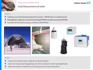
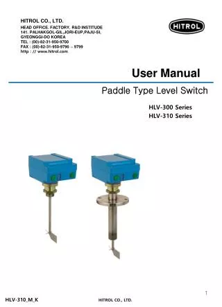
Vibrating Fork Level Limit Switch for Solids
u201cTrumen Technologies Pvt. Ltd.u201d is an ISO 9001:2015 certified ,Indian based Manufacturer and Exporters of Level and Pressure sensing instruments. We at Trumen is a team of professionals having years of experience in Level and Pressure Instruments manufacturing who understands what customer needs, and try to fulfill those requirements in appropriate time with best Quality.<br> We have wide range of CE certified product like Radar Level Transmitters, Ultrasonic Level ,Vibrating fork solid level switch, Vibrating fork liquid level switch, Admittance point level switch, Capacitance point level switch

Vibrating Fork Level Limit Switch for Solids
E N D
Presentation Transcript
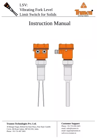
LSV: Vibrating Fork Level Limit Switch for Solids ® sensing matters Instruction Manual Customer Support Phone: +91-731-656 2425 email: sales@trumen.in email: support@trumen.in web:www.trumen.in Trumen Technologies Pvt. Ltd. 39 Mangal Nagar, Behind Sai Ram Plaza, Near Rajiv Gandhi Circle, AB Road, Indore, MP 452 001, India Phone: +91-731-497 2065
® sensing matters List of content Page 1 Operating Principle..................................................................................................................... Technical Specification................................................................................................................ Do's and Don'ts............................................................................................................................ Troubleshooting........................................................................................................................... Maintenance & Spares............................................................................................... Annexure-1 2 3 4 4 Introduction - LSV-UD-D1/D2/D3 (Order code EIUD / ERUD).................................... Page1 Page1 controls & indicators, connection terminals, configuration switches......................... Page2 Operation Matrix - LSV-UD-D1/D2/D3 (EIUD / ERUD)................................................ Electrical Connections - LSV-UD-D1/D2/D3 (EIUD / ERUD)........................................ Page3 Annexure-2 Introduction - LSV-DP-D1/D2/D3 (Order code EIDP / ERDP)...................................... Page1 Page1 controls & indicators, connection terminals, configuration switches......................... Page2 Operation Matrix - LSV-DP-D1/D2/D3 (EIDP / ERDP)................................................. Electrical Connections - LSV-DP-D1/D2/D3 (EIDP / ERDP)......................................... Page3 Annexure-3 Introduction - LSV-U(S+P)-D1/D2/D3 (Order code EIUSP / ERUSP).......................... Page1 Page1 controls & indicators, connection terminals, configuration switches......................... Page2 Operation Matrix - LSV-U(S+P)-D1/D2/D3 (EIUSP / ERUSP)...................................... Electrical Connections - LSV-U(S+P)-D1/D2/D3 (EIUSP / ERUSP).............................. Page3 Annexure-4 Introduction - LSV-AR-D1/D2/D3 (Order code EIAR).................................................. Page1 Page1 controls & indicators, connection terminals, configuration switches......................... Page2 Operation Matrix - LSV-AR-D1/D2/D3 (EIAR).............................................................. Electrical Connections - LSV-AR-D1/D2/D3 (EIAR)...................................................... Page3 Annexure-5 Introduction - LSV-DL-D1/D2/D3 (Order code EIDL)................................................... Page1 Page1 controls & indicators, connection terminals, configuration switches......................... Page2 Operation Matrix - LSV-DL-D1/D2/D3 (EIDL).............................................................. Electrical Connections - LSV-DL-D1/D2/D3 (EIDL)....................................................... Page3
Operating Principle Electronics of LSV excites the piezo-electric-crystals inside the tuning fork, which makes the fork tines vibrate at their natural resonance frequency in free air. Amplitudes of vibration are above threshold when the tines are free to vibrate. When material touches the fork tines, vibration stops as the resonance gets disturbed. Amplitudes of vibration, as sensed by electronics falls below the threshold strength and material presence is thus detected. lsv-manual-page01 www.trumen.in 1
Technical Specification Features Specifications EIUD / ERUD Supply & Output Integral / Remote Electronics Universal Power Supply, DPDT Relay Output 15 to 80 VDC and 15 to 260 VAC 50/60Hz Potential Free DPDT Relay Output 5 A each @ 24VDC or 220VAC 1. Fast Switching Response 2 sec (0.8 sec and 1.5 sec available on demand) 2. 1" screw mountings available Relay Type and Rating 3. High pressure 15 bar forks 4. High Tempreture up-to 250°C available 5. Calibration-less operation EIDP / ERDP Supply & Output Output Limit Integral / Remote Electronics for PNP Output 12 to 60 VDC, PNP 250mA max. Short Circuit Safe 6. Remote electronics with std 10 meters cable length 7. Tropicalized & potted electronics module 8. Threaded & Flanged Mountings EIUSP / ERUSP Supply & Output Integral / Remote Electronics SPDT + PNP Output Universal Supply for SPDT Output 15 to 80 VDC 15 to 260 VAC 50/60Hz DC Supply for PNP Output 15 to 60 VDC Potential Free DPDT Relay Output 5 A each @ 24VDC or 220VAC 250mA max. Short Circuit Safe 9. Electronic Inserts support all requirements 10. Ingress protection : IP 68/66 (as per IS-13947) 11. Ex-proof (Ex d T6 IP-66 IIC ) - Flameproof as per IS/IEC 60079-1:2007 - Weatherproof (IP-66) as per IS/IEC 60529:2001 Relay Type and Rating - Suitable for Gas Group : IIC - Suitable for Zone 1 & 2 atmospheres PNP Output 12. Compact size EIAR Supply & Output Integral Electronics AC series relay Two Wire 18 to 260 VAC, Series Relay not less than 4mA to release external relay maximum 150mA to magnetize relay Use relays/contactors will more than 4mA holding current 13. Low power consumption (0.5 to 0.7VA) Applications Output Limit 1. Free flowing powders and granules (size max. 10mm) 2. Suitable for side as well as top mounting EIDL Supply & Output Integral Electronics 4-20mA Loop Powered Two Wire DC 8 / 16 mA 12 to 60 VDC 8mA (±1mA max) / 16mA (±1mA max) 3. Minimum and maximum failsafe field selectable 4. Process temperature max 250°C Output Limit 5. Process pressure max. 15 bar Sensor Cable Remote electronics require special cable from fork to controller. 10 meter standard length more available on demand Typical Mountings Min. Density 15 gram/litre for D1 (Fork length 150mm) 75 gram/litre for D2 (Fork length 125mm) 500 gram/litre for D3 (Fork length 100mm) special interconnection cable wall/pipe mounting Ambient Temp. -20°C ... 70°C (-4°F ... 158 °F) remote electronics Process Temp. -20°C ... 80°C (-4°F ... 176 °F) Extended Process Temperature -30°C ... 200°C (-22°F ... 392 °F) {250°C available on request} (extensions & heat sinks required) Process Pressure absolute / max. 15 bar Wetted Parts SS 316 or SS 316L Mountings NPT / BSP 1", 1¼", 1½", 2" etc Flanged : ANSI/JIS/DIN/ASA/custom Extensions Tube Material & Length SS 304, SS 316, SS 316L 125mm to 3,000mm Specifications are subject to change without prior notice lsv-manual-page02 www.trumen.in 2
Do's and Don'ts Features Installation Precaution 1. Always connect the "Earth" to the external "Earthing" screw 1 3 2. Tighten the cable entries & glands properly 2 3. Secure the top aluminium cover at its place properly once the electrical connections and other settings are completed 4. Always tighten the process connection using proper wrench never try to tight by rotating the aluminium housing 4 5. Make sure process connection is same as that in hopper/tank 5 6. Vibrating fork tines:- 6.1 Should never be bent closer 6.2 Should never be bent apart 6.3 Should never be cut or machined in any way 6.4 Should never be extended by welding or machining 6 7. Cable entries must face downwards only 8. Nozzles should never be longer than the fork extension 9. If mounted directly under the material entry, always install a cannopy of suitable strength at proper height from the fork 10. Never climb either by gripping or stepping over either the fork tines or its aluminium housing 11. Obeserve other safety precautions as required at the place of application lsv-manual-page03 www.trumen.in 3
Troubleshooting Indication Probable cause Work-around Solution No switching output or Power is not available See if 'power' LED is ON Sensor electronic insert is needed to be replaced. sensor is permanently in alarm If power LED is OFF check voltage on terminal 1 and 2 Proper voltage is available but 'power' LED is still OFF Power section of sensor electronic insert is failed Fork is not vibrating when fork tines are touched by hand Sensor electronic insert fork oscillator failed Fork is vibrating but no switching output when fork tines are touched by hand Sensor electronic insert evaluation section failure Abrupt switching Material is agitated Set time delay to 5 second in both dry and wet condition (turn switch 2, 3 ON) Time delay solves switching issues in agitated materials. Device shows no material after some time even when fork is inside the material Material fluffy or fork rate-holes the material due to its own vibrations Set device in sensitive mode (turn switch 1 ON) Sensitive setting reduces vibrational strength and makes switching point at lower amplitude. Fork settings are all OK but fork fails to switch to 'no material' at random times Power supply carrying extra noise and fork amplifier picking the noise Make necessary arrangements to filter the noise in power-line before being fed to the device Device contains sufficient filtering of power supply noise inside, but sometimes external earth is needed to make filters sink the extra power supply noise back to earth. Provide an exclusive earthing to terminal# 3, fork enclosure earthing screw and fork process connection (device mounting screw or flange) Select proper fork surface while ordering as per service material to mitigate fork errosion as well as deposition Device worked for few months / years but now fails to switch with respect to material while power conditions are all same Device senses fork frequency and amplitude to ascertain presence/absense of material. Possible reasons are Care is needed to be taken while ordering. Scheduled cleaning of fork tines in sticky material application is recommended. Order device of proper thermal grade for proper service life of device 1. Fork frequency shift due to fork wear/ errosion by service material Applications In case of fork tine wear or temperature stress, fork sensor is needed to be replaced. Clean up deposited materials on fork tines as a part of maintenance schedule 2. Material deposition on fork leads 3. Over temperature of service material causing fork drive damage Maintenance and Spares Shown on the left are various parts of LSV level switch. Separatable parts are Top Cover Electronic Insert connection terminals electronic insert fixing screw 1. Electronic insert in short called 'electronics' 2. Fork + Enclosure + Cover + Glands collectively called 'mechanical' 4-way male connector for sensor (fork) 4-way female connector from sensor (fork) For maintenance issues involving replacement of 'electronics', just a single fixing screw is needed to be released. Device enclosure Cable glands Lift the electronics slowly by holding electronics with one hand and mechanical with other, as wires are connected using rigid 4-way connectors to it. Thermal spacer (where needed) Disconnect 4-way connector by holding electronics with one hand and female of connector by other hand, while the rest of the device is at rest. Process connection Fork extension (longer for low level) Connect the new replaced sensor. 4-way connector is unidirectional and only connects in proper direction. Set the electronics properly to its position. Fork tines Match the mounting screw hole of electronics with that of enclosure and fix the screw. For mechanical issues please send the entire device back to Trumen. lsv-manual-page04 www.trumen.in 4
Annexure-1 Introduction - LSV-UD-D1/D2/D3 (EIUD / ERUD) LSV-UD-D1 LSV-UD-D2 LSV-UD-D3 controls & indicators A Alarm Indicating LED B Configuration Switches C Power ON LED Indicator D Connecting Terminals E External Earthing Terminal B A LSV-UD C turn-on E to set ON connection terminals status power sensitive dry delay wet delay min failsafe 5 sec 15... 80 VDC 15... 260 VAC U 1 + of DC or Live of AC Supply input 2 - of DC or Neutral of AC Supply input Supply: 15 to 80VDC or 15 to 260VAC 50/60Hz D L1 N 1 2 3 4 5 6 7 8 9 3 Earth terminal for safety 4 Normally connected terminal of contact 1 5 Common terminal of contact 1 6 Normally open terminal of contact 1 7 Normally connected terminal of contact 2 8 Common terminal of contact 2 9 Normally open terminal of contact 2 configuration switches 1 sensitivity control sensitive setting for low density materials (turn-on for fluffy/low density powders etc) (keep turned-off for normal density materials) LSV-UD-D1/D2/D3 OFF Position turn-on to set ON Position 2 “dry” (or uncovered) delay (5 second delay) setting (turn-on when 5 second more time is needed for fork out of material confirmation) sensitive dry delay wet delay min failsafe 5 sec 3 “wet” (or covered) delay (5 second delay) setting (turn-on when 5 second more time is needed for fork dipped in the material confirmation) 4 minimum failsafe select Failsafe means alarm is same as power failure. Turn on for underflow detection (min. failsafe) Keep turned off for overflow detection (max. failsafe) ON Position OFF Position Example of Switch in On and Off Positions lsv-manual-annexure-1 www.trumen.in Page 1
Annexure-1 Operation Matrix - LSV-UD-D1/D2/D3 (EIUD / ERUD) Failsafe defines that the alarm and power failure / device failure conditions are same to the external system. Failsafe operation is best understood with the type of installation and following matrix. DPDT Relay Contacts Material & Installation Material Status Failsafe Setting Status LED Power ON Power OFF Off No material at high level. ON 1 2 3 4 Indicating normal or healthy status. 4 5 6 7 8 9 4 5 6 7 8 9 min failsafe High level / overflow detection Switch no. 4 is off, failsafe high/maximum Relay ON normal or healthy contacts. Relay OFF alarm contacts. (due to power failure) Material is above the high level or fork is covered with material. On ON 1 2 3 4 4 5 6 7 8 9 4 5 6 7 8 9 Indicating alarm status. min failsafe Relay OFF alarm contacts. Relay OFF alarm contacts. (as it is) Switch no. 4 is off, failsafe high/maximum No material at low level. On ON 1 2 3 4 4 5 6 7 8 9 Relay OFF alarm contacts. 4 5 6 7 8 9 Indicating alarm status. Low level / underflow detection min failsafe Relay OFF alarm contacts. (as it is) Switch no. 4 is on, failsafe low/minimum Material is above the low level or fork is covered with material. Off ON 1 2 3 4 Indicating normal or healthy status. 4 5 6 7 8 9 4 5 6 7 8 9 min failsafe Relay ON normal or healthy contacts. Relay OFF alarm contacts. (due to power failure) Switch no. 4 is on, failsafe low/minimum lsv-manual-annexure-1 www.trumen.in Page 2
Annexure-1 Electrical Connections - LSV-UD-D1/D2/D3 (EIUD / ERUD) electrical connections (AC) electrical connections (DC) LSV-UD LSV-UD turn-on turn-on to set to set ON ON status power status power sensitive dry delay wet delay min failsafe sensitive dry delay wet delay min failsafe 15... 80V DC 15... 260V AC 15... 80V DC 15... 260V AC U U L1 N L1 N 1 2 3 4 5 6 7 8 9 1 2 3 4 5 6 7 8 9 Live output contact 1 output contact 2 output contact 1 output contact 2 DC Neutral 15 to 260 VAC 50/60 Hz 15 to 80 VDC Remote probe connections for LSV-UD-D1/D2 (ERUD) LSV-UD-D3 (ERUD) LSV-UD LSV-D3 LSV-D1/D2 turn-on to set 1 2 3 Red 1 2 3 4 ON status power sensitive dry delay wet delay min failsafe Black 5 sec Red Black Green White White 15... 80 VDC 15... 260 VAC U L1 N 1 2 3 4 5 6 7 8 9 Proper connection to supply earth terminal (3) and the external earth terminal (screw) is must. lsv-manual-annexure-1 www.trumen.in Page 3
Annexure-2 Introduction - LSV-DP-D1/D2/D3 (EIDP / ERDP) controls & indicators LSV-DP-D1 LSV-DP-D2 LSV-DP-D3 A Alarm Indicating LED B Configuration Switches C Power ON LED Indicator D Connecting Terminals E External Earthing Terminal B A LSV-DP C E turn-on to set connection terminals ON status power sensitive dry delay wet delay 5 sec min failsafe 1 + of DC Supply input 2 - of DC Supply input Supply: 12 to 60VDC PNP (alarm=float) D U 12 to 60V DC 1 2 3 4 5 6 7 8 9 3 Earth terminal for safety 4 PNP output is supplied with voltage 12 to 60VDC configuration switches 1 sensitivity control sensitive setting for low density materials (turn-on for fluffy/ low density powders etc) (keep turned-off for normal density materials) LSV-DP-D1/D2/D3 OFF Position turn-on to set ON Position 2 “dry” (or uncovered) delay (5 second delay) setting (turn-on when 5 second more time is needed for fork out of material confirmation) sensitive dry delay wet delay min failsafe 5 sec 3 “wet” (or covered) delay (5 second delay) setting (turn-on when 5 second more time is needed for fork dipped in the material confirmation) 4 minimum failsafe select Failsafe means alarm is same as power failure. Turn on for underflow detection (min. failsafe) Keep turned off for overflow detection (max. failsafe) ON Position OFF Position Example of Switch in On and Off Positions lsv-manual-annexure-2 www.trumen.in Page 1
Annexure-2 Operation Matrix - LSV-DP-D1/D2/D3 (EIDP / ERDP) Vibrating fork is a single element tuned mechanical element type level sensing device. Failsafe defines that the alarm and power failure / device failure conditions are same to the external system. Failsafe operation is best understood with the type of installation and following matrix. PNP Output Material & Installation Material Status Failsafe Setting Status LED Power ON Power OFF Off No material at high level. 1 2 3 4 1 2 3 4 Indicating normal or healthy status. ON 1 2 3 4 IL Ileak min failsafe Ileak ≤ 0.1mA High level / overflow detection IL(max) = 250mA Switch no. 4 is off, failsafe high/maximum. Normal or healthy output. Alarm output. (due to power failure) Material is above the high level or fork is covered with material. 1 2 3 4 1 2 3 4 On ON 1 2 3 4 Ileak Ileak Indicating alarm status. min failsafe Ileak ≤ 0.1mA Alarm output. (as it is) Ileak ≤ 0.1mA Alarm output. Switch no. 4 is off, failsafe high/maximum. No material at low level. 1 2 3 4 1 2 3 4 On ON 1 2 3 4 Ileak Ileak Indicating alarm status. min failsafe Ileak ≤ 0.1mA Alarm output. Ileak ≤ 0.1mA Alarm output. (as it is) Low level / underflow detection Switch no. 4 is on, failsafe low/minimum. Material is above the low level or fork is covered with material. Off 1 2 3 4 1 2 3 4 ON Indicating normal or healthy status. 1 2 3 4 IL Ileak Ileak ≤ 0.1mA Alarm output. (due to power failure) IL(max) = 250mA Normal or healthy output. min failsafe Switch no. 4 is on, failsafe low/minimum. lsv-manual-annexure-2 www.trumen.in Page 2
Annexure-2 Electrical Connections - LSV-DP-D1/D2/D3 (EIDP / ERDP) electrical connections (DC) LSV-DP turn-on to set ON status power sensitive dry delay wet delay 5 sec min failsafe PNP (alarm=float) U 12 to 60V DC 1 2 3 4 5 6 7 8 9 output unused terminals DC 12 to 60 VDC Remote probe connections for LSV-DP-D1/D2 (ERDP) LSV-DP-D3 (ERDP) LSV-DP LSV-D3 LSV-D1/D2 turn-on to set 1 2 3 4 1 2 3 Red ON status power sensitive dry delay wet delay 5 sec Black Red Black Green White White min failsafe PNP (alarm=float) U 12 to 60V DC 1 2 3 4 5 6 7 8 9 Proper connection to supply earth terminal (3) and the external earth terminal (screw) is must. lsv-manual-annexure-2 www.trumen.in Page 3
Annexure-3 Introduction - LSV-U(S+P)-D1/D2/D3 (EIUSP / ERUSP) controls & indicators LSV-U(S+P)-D1 LSV-U(S+P)-D2 LSV-U(S+P)-D3 A Alarm Indicating LED B Configuration Switches C Power ON LED Indicator D Connecting Terminals E External Earthing Terminal B A LSV-U(S+P) C turn-on E to set connection terminals ON status power sensitive dry delay wet delay min failsafe 5 Sec 15... 80V DC 15... 260V AC U 1 (+) of DC or Live of AC Supply input 2 (-) of DC or Neutral of AC Supply input Supply: 15 to 80VDC or 15 to 260VAC 50/60Hz 3 Earth terminal for safety 4 Normally connected terminal of SPDT contact 5 Common terminal of SPDT contact 6 Normally open terminal of SPDT contact 7 (-) of DC for PNP output 8 (+) of DC for PNP output 9 DC PNP output with respect to -ve of DC Supply should be within 15 to 60VDC for PNP output U ! 15... 60V DC L1 N less than 60VDC only D PNP o/p 1 2 3 4 5 6 7 8 9 ! configuration switches 1 sensitivity control sensitive setting for low density materials (turn-on for fluffy/low density materials) (keep turned-off for normal materials) LSV-U(S+P)-D1/D2/D3 OFF Position turn-on to set ON Position 2 “dry” (or uncovered) delay (5 second delay) (turn-on when 5 second more time is needed for fork out of material confirmation) sensitive dry delay wet delay min failsafe 5 Sec 3 “wet” (or covered) delay (5 second delay) (turn-on when 5 second more time is needed for fork dipped in the material confirmation) 4 minimum failsafe select Failsafe means alarm is same as power failure. Turn on for underflow detection (min. failsafe) Keep turned off for overflow detection (max. failsafe) ON Position OFF Position Example of Switch in On and Off Positions lsv-manual-annexure-3 www.trumen.in Page 1
Annexure-3 Operation Matrix - LSV-U(S+P)-D1/D2/D3 (EIUSP / ERUSP) Failsafe defines that the alarm and power failure / device failure conditions are same to the external system. Failsafe operation is best understood with the type of installation and following matrix. Material & Installation Material Status Failsafe Setting Status LED Relay Contacts & PNP Output Power ON Power OFF No material at high level. Off ON 1 2 3 4 Indicating normal or healthy status. 4 5 6 4 5 6 min failsafe Switch no. 4 is off, failsafe high/maximum Relay ON normal or healthy contacts. Relay OFF alarm contacts. (due to power failure) High level / overflow detection 7 8 9 7 8 9 Ileak IL IL(max) = 250mA Ileak ≤ 0.1mA Material is above the high level or fork is covered with material. On ON 1 2 3 4 4 5 6 4 5 6 Indicating alarm status. Relay OFF alarm contacts. Relay OFF alarm contacts. (as it is) min failsafe Switch no. 4 is off, failsafe high/maximum 7 8 9 7 8 9 Ileak Ileak Ileak ≤ 0.1mA Ileak ≤ 0.1mA No material at low level. On ON 1 2 3 4 4 5 6 4 5 6 Indicating alarm status. Relay OFF alarm contacts. Relay OFF alarm contacts. (as it is) min failsafe Low level / underflow detection Switch no. 4 is on, failsafe low/minimum 7 8 9 7 8 9 Ileak Ileak Ileak ≤ 0.1mA Ileak ≤ 0.1mA Material is above the low level or fork is covered with material. Off ON 1 2 3 4 4 5 6 4 5 6 Indicating normal or healthy status. Relay ON normal or healthy contacts. Relay OFF alarm contacts. (due to power failure) min failsafe Switch no. 4 is on, failsafe low/minimum 7 8 9 7 8 9 Ileak IL IL(max) = 250mA Ileak ≤ 0.1mA lsv-manual-annexure-3 www.trumen.in Page 2
Annexure-3 Electrical Connections - LSV-U(S+P)-D1/D2/D3 (EIUSP / ERUSP) electrical connections (AC) electrical connections (DC) LSV-U(S+P) LSV-U(S+P) turn-on turn-on to set to set ON ON status power status power sensitive dry delay wet delay min failsafe sensitive dry delay wet delay min failsafe 5 Sec 5 Sec 15... 80V DC 15... 260V AC 15... 80V DC 15... 260V AC U U U U ! ! 15... 60V DC 15... 60V DC L1 N L1 N less than 60VDC only less than 60VDC only PNP o/p PNP o/p 1 2 3 4 5 6 7 8 9 1 2 3 4 5 6 7 8 9 Live output contact output contact PNP output PNP output DC Neutral 15 to 260 VAC 50/60 Hz 15 to 60 VDC Remote probe connections for LSV-U(S+P)-D1/D2 (ERUSP) LSV-U(S+P)-D3 (ERUSP) LSV-U(S+P) LSV-D3 LSV-D1/D2 turn-on to set 1 2 3 Red 1 2 3 4 ON status power sensitive dry delay wet delay min failsafe 5 Sec Black Red Black Green White White 15... 80V DC 15... 260V AC U U ! 15... 60V DC L1 N less than 60VDC only PNP o/p 1 2 3 4 5 6 7 8 9 Proper connection to supply earth terminal (3) and the external earth terminal (screw) is must. lsv-manual-annexure-3 www.trumen.in Page 3
Annexure-4 Introduction - LSV-AR-D1/D2/D3 (EIAR) controls & indicators LSV-AR-D1 LSV-AR-D2 LSV-AR-D3 A Alarm Indicating LED B Configuration Switches C Normal LED Indicator D Connecting Terminals E External Earthing Terminal B A E LSV-AR C turn-on to set connection terminals ON normal alarm x 5 sec dry delay wet delay min failsafe 1 Live of AC Supply through fuse 2 Neutral of AC Supply input through specified series relay 18 to 260VAC 50/60 Hz series 2 wire AC series Relay (<5mA holding current) D U 18... 260V AC 1 2 3 4 5 6 7 8 9 3 Earth terminal for safety 4,5,6,7,8,9 Not used configuration switches 1 Not used LSV-AR-D1/D2/D3 OFF Position 2 “dry” (or uncovered) delay (5 second delay) setting (turn-on when 5 second more time is needed for fork out of material confirmation) turn-on to set ON Position x 3 “wet” (or covered) delay (5 second delay) setting (turn-on when 5 second more time is needed for fork dipped in the material confirmation) 5 sec dry delay wet delay min failsafe 4 minimum failsafe select Failsafe means alarm is same as power failure. Turn on for underflow detection (min. failsafe) Keep turned off for overflow detection (max. failsafe) ON Position OFF Position Example of Switch in On and Off Positions lsv-manual-annexure-4 www.trumen.in Page 1
Annexure-4 Operation Matrix - LSV-AR-D1/D2/D3 (EIAR) Series relay will be energized in normal or healthy condition. Series relay will be de- energized in alarm condition. Failsafe defines that the alarm and power failure / device failure conditions are same to the external system. Failsafe operation is best understood with the type of installation and following matrix. Series Relay Status Material & Installation Switching Operation Failsafe Setting Status LED Alarm/ Normal Power ON Power OFF When switch no. 4 is off (failsafe high / maximum). output status shows normal when there is no material at high switch point or fork is out of the material. Red 1 2 1 2 Off ON Normal or healthy 1 2 3 4 High level / overflow detection L N L N Green Series relay on Series relay off (due to power failure) min failsafe On Red When switch no. 4 is off (failsafe high / maximum). output status shows alarm if fork is dipped in material at high switch point. 1 2 1 2 ON 1 2 3 4 On Alarm L N L N min failsafe Series relay off Series relay off (as it is) Green Off Red When switch no. 4 is on (failsafe low / minimum). output status shows alarm when there is no material at low switch point or fork is out of the material. 1 2 1 2 ON On 1 2 3 4 Low level / underflow detection L N L N Alarm min failsafe Series relay off Series relay off (as it is) Green Off Red When switch no. 4 is on (failsafe low / minimum). output status shows normal if fork is dipped in material at low switch point. 1 2 1 2 Off ON 1 2 3 4 Normal or healthy L N L N min failsafe Green Series relay on Series relay off (due to power failure) On lsv-manual-annexure-4 www.trumen.in Page 2
Annexure-4 Electrical Connections - LSV-AR-D1/D2/D3 (EIAR) electrical connections (AC) LSV-AR turn-on to set ON normal alarm x 5 sec dry delay wet delay min failsafe 2 wire AC series Relay (<5mA holding current) U 18... 260V AC 1 2 3 4 5 6 7 8 9 L Not Used AC Supply 18 to 260 VAC N Specified AC Series Relay Use AC relay / contactor having maximum 150mA to magnetize and holding current should not be less than 4mA. Voltage rating of AC relay should be as per input supply voltage. LSV-AR turn-on to set ON normal alarm x 5 sec dry delay wet delay min failsafe 2 wire AC series Relay (<5mA holding current) U 18... 260V AC 1 2 3 4 5 6 7 8 9 Proper connection to supply earth terminal (3) and the external earth terminal (screw) is must. lsv-manual-annexure-4 www.trumen.in Page 3
Annexure-5 Introduction - LSV-DL-D1/D2/D3 (EIDL) 8/16 mA Output LSV-DL-D1 LSV-DL-D2 LSV-DL-D3 controls & indicators A Alarm Indicating LED B Configuration Switches C Power ON LED Indicator D Connecting Terminals E External Earthing Terminal B A E LSV-DL- 8/16 C turn-on to set ON alarm power sensitive dry delay wet delay connection terminals 5 sec min failsafe Loop powered 8mA ± 1mA (alarm) 16mA ± 1mA (normal) D 12 to 60V DC U 1 (+) of DC Supply input 2 (-) of DC Supply input DC Supply: 12 to 60VDC 1 2 3 4 5 6 7 8 9 3 Earth terminal for safety 4,5,6,7,8,9 Not used configuration switches 1 sensitivity control sensitive setting for low density materials (turn-on for fluffy / low density materials etc.) (keep turned-off for normal density materials) LSV-DL-8/16 OFF Position turn-on to set ON Position 2 “dry” (or uncovered) delay (5 second delay) setting (turn-on when 5 second more time is needed for fork out of material confirmation) sensitive dry delay wet delay min failsafe 5 sec 3 “wet” (or covered) delay (5 second delay) setting (turn-on when 5 second more time is needed for fork dipped in the material confirmation) 4 minimum failsafe select Failsafe means alarm is same as power failure. Turn on for underflow detection (min. failsafe) Keep turned off for overflow detection (max. failsafe) ON Position OFF Position Example of Switch in On and Off Positions lsv-manual-annexure-5 www.trumen.in Page 1
Annexure-5 Operation Matrix - LSV-DL-D1/D2/D3 (EIDL) Miliampere output 16 is supplied in normal or healthy condition. Miliampere output 8 is supplied in alarm condition. Failsafe defines that the alarm and power failure / device failure conditions are same to the external system. Failsafe operation is best understood with the type of installation and following matrix. Material & Installation Switching Operation Failsafe Setting Status LED Miliampere Output Status When switch no. 4 is off (failsafe high / maximum). output status shows normal when there is no material at high switch point or fork is out of the material. Off 1 2 ON 1 2 3 4 IL IL Normal High level / overflow detection DC min failsafe IL = 16mA When switch no. 4 is off (failsafe high / maximum). output status shows alarm if fork is dipped in material at high switch point. On 1 2 ON 1 2 3 4 IL IL Alarm DC min failsafe IL = 8mA When switch no. 4 is on (failsafe low / minimum). output status shows alarm when there is no material at low switch point or fork is out of the material. On 1 2 ON 1 2 3 4 Low level / underflow detection IL IL Alarm DC min failsafe IL = 8mA When switch no. 4 is on (failsafe low / minimum). output status shows normal if fork is dipped in material at low switch point. Off 1 2 ON 1 2 3 4 IL IL DC Normal min failsafe IL = 16mA lsv-manual-annexure-5 www.trumen.in Page 2
Annexure-5 Electrical Connections - LSV-DL-D1/D2/D3 (EIDL) electrical connections (DC) LSV-DL- 8/16 turn-on to set ON alarm power sensitive dry delay wet delay 5 sec min failsafe Loop powered 8mA ±1mA (alarm) 16mA ±1mA (normal) 12 to 60V DC U 1 2 3 4 5 6 7 8 9 Not used mA Supply 12 to 60 VDC Meter/Indicator/PLC/SCADA LSV-DL- 8/16 turn-on to set ON alarm power sensitive dry delay wet delay 5 sec min failsafe Loop powered 8mA ± 1mA (alarm) 16mA ± 1mA (normal) 12 to 60V DC U 1 2 3 4 5 6 7 8 9 Proper connection to supply earth terminal (3) and the external earth terminal (screw) is must. lsv-manual-annexure-5 www.trumen.in Page 3