Download
1 / 40
400 likes | 420 Vues
Vibrating fork sensor vibranivou00ae vn 1020 for point level measurement Supplier, Exporter in India<br>For More Information visit on:- www.seeautomation.com<br>Our Mail I.D:- sales@seeautomation.com<br>Contact Us:- 91-11-22012324 , 8144883403<br>

E N D
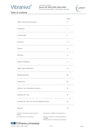
1 Level limit switch Series VN 1000 / 2000 / 5000 / 6000 Technical information / Instruction manual ® Vibranivo Table of contents 2 Page Safety notes/ Technical support 2 --------------------------------------------------------------------------------------------------------- 3 Introduction 3 --------------------------------------------------------------------------------------------------------- Technical data 4 4 --------------------------------------------------------------------------------------------------------- Approvals 12 --------------------------------------------------------------------------------------------------------- 5 Options 13 --------------------------------------------------------------------------------------------------------- Mounting 14 --------------------------------------------------------------------------------------------------------- 6 Electrical installation 17 --------------------------------------------------------------------------------------------------------- Signal output/ Diagnostics 23 7 --------------------------------------------------------------------------------------------------------- Settings Sensitivity 28 --------------------------------------------------------------------------------------------------------- 8 Maintenance --------------------------------------------------------------------------------------------------------- 29 Notes for use in Hazardous Locations 30 9 --------------------------------------------------------------------------------------------------------- Assembly VN ..040 33 --------------------------------------------------------------------------------------------------------- Assembly VN ..020/ VN ..030 with separate housing 38 10 --------------------------------------------------------------------------------------------------------- Disposal 40 11 Subject to technical change and price change. We assume no liability for typing errors. All dimensions in mm (inches). Different variations to those specified are possible. Please contact our technical consultants. 12 VN 1000 / 2000 / 5000 / 6000 f gi180713 page 1
1 Level limit switch Series VN 1000 / 2000 / 5000 / 6000 Technical information / Instruction manual ® Vibranivo Safety notes / Technical support 2 Notes • Installation, maintenance and commissioning must be carried out only by qualified technical personnel. • The product must be used only in the manner outlined in this instruction manual. 3 Special attention must be paid to warnings and notes as follows: WARNING 4 Relates to a caution symbol on the product and means, that a failure to observe the necessary precautions can result in death, serious injury and/ or considerable material damage. WARNING 5 Relates to a caution symbol on the product: Risk of electric shock WARNING 6 Relates to a caution symbol on the product and means, that a failure to observe the necessary precautions can result in death, serious injury and/ or considerable material damage. This symbol is used, when there is no corresponding caution symbol on the product. 7 A failure to observe the necessary precautions can result in considerable material damage. CAUTION Safety symbols 8 In manual and on product Description CAUTION: refer to accompanying documents (manual) for details. 9 Earth (ground) Terminal Protective Conductor Terminal 10 Technical support Please contact your local supplier (see www.uwt.de for address). Otherwise you can contact: UWT GmbH Westendstr. 5 87488 Betzigau Germany Tel. 0049 (0)831 57123-0 Fax. 0049 (0)831 76879 info@uwt.de www.uwt.de 11 12 gi180713 VN 1000 / 2000 / 5000 / 6000 f 2 page
1 Level limit switch Series VN 1000 / 2000 / 5000 / 6000 Technical information / Instruction manual ® Vibranivo Introduction 2 Applications The VIBRANIVO oscillating probe is normally screwed into the lateral container wall so that it is level with the filling height to be registered and monitored. The device is used for level monitoring in all types of containers and silos. It can be used with all powdery and granulated bulk materials that do not show a strong tendency to form crusts or deposits. Detection of solids in water is also possible. The device can also be mounted from the top of the container. In this case an extension piece is used to mount the probe level with the height to be registered. 3 The units can be delivered with a wide range of Ex-approvals for use in Gas and Dust Hazardous Areas. The length of the probe can be up to 4 m (157”) with an extension tube (VN ..030) or up to 20 m (787”) with an extension rope (VN 2050/ 6050). A selection of fields of application: 4 The use of a sliding sleeve is recommended so that the switch point can be changed easily during operation of the device. • Building materials industry lime, styrofoam, moulding sand, etc. • Food industry milk powder, flour, salt, etc. Function • Plastics industry plastics granules etc. The piezo-electrically stimulated oscillating fork vibrates at its mechanical resonance frequency. If the probe is covered by the bulk material, the damping thus generated is registered electronically and a corresponding signal output is actuated. The oscillation of the fork ensures a certain self-cleaning. 5 • • • Timber industry Chemical industry Mechanical engineering 6 Detection of solids in water Detection of solids VN ..030 VN ..040 VN 1030 VN 5030 7 VN ..050 optional sliding sleeve 8 VN 1020 VN 1030 VN ..020 VN ..030 VN ..040 VN 5020 VN 5030 9 10 VN 1020 VN 5020 VN ..020 VN 1020 VN 5020 VN ..020 11 Application in down pipe Application in down pipe 12 VN 1000 / 2000 / 5000 / 6000 f gi180713 page 3
1 Level limit switch Series VN 1000 / 2000 / 5000 / 6000 Technical information / Instruction manual ® Vibranivo Technical data 2 Housing versions Series VN 1000/ 2000 Standard 3 4 Series VN 5000/ 6000 Standard 5 6 de Explosionproof with increased safety terminal box 7 8 9 d Flameproof/ explosionproof 10 11 12 gi180713 VN 1000 / 2000 / 5000 / 6000 f 4 page
1 Level limit switch Series VN 1000 / 2000 / 5000 / 6000 Technical information / Instruction manual ® Vibranivo Technical Data 2 Extensions VN ..020 3 4 5 Thread Triclamp Flange Temperature extended shaft (pos.3 2) Option: Separate housing (pos.26 1/ pos.26 2) Cap nut: see page 15 6 L without option with option: enhanced sensitivity (pos.26 x) Vibrasil 70 (pos.26 a) Vibrasil 90 (pos.26 b) VN 1020 VN 5020 165 mm (6.5“) 7 VN 2020 VN 6020 235 mm (9.25”) 260 mm (9.84“) * see page 6 bottom right ** Welding seam max. ø43.8 mm (ø1.72") VN ..030 8 9 10 11 Triclamp With option separate housing (pos.26 1/ pos.26 2) Thread Flange Temperature extended shaft (pos.3 2) * see page 6 below right hand ** Welding seam max. ø43.8 mm (ø1.72") Cap nut: see page 16 12 VN 1000 / 2000 / 5000 / 6000 f gi180713 page 5
1 Level limit switch Series VN 1000 / 2000 / 5000 / 6000 Technical information / Instruction manual ® Vibranivo Technical data 2 VN ..040 Pos. 5 L 5 M 5 S 5 T 5 U G 1" G 1" G 1" NPT 1" NPT 1" NPT 1" 3 Pos. 5 A 5 B G 1" NPT 1" G 1" 4 Extension tube NOT part of delivery 5 Thread Flange Triclamp 6 * see bottom right ** Welding seam max. ø43.8 mm (ø1.72") VN ..050 * Length of oscillating rods 7 VN 10..0 VN 50..0 VN 20..0 VN 60..0 8 9 with option Enhanced sensitivity (pos.26 x) Vibrasil® 70 (pos.26 a) Vibrasil® 90 (pos.26 b) 10 11 Thread Flange * see right ** Welding seam max. ø43.8 mm (ø1.72") 12 gi180713 VN 1000 / 2000 / 5000 / 6000 f 6 page
1 Level limit switch Series VN 1000 / 2000 / 5000 / 6000 Technical information / Instruction manual ® Vibranivo Technical data 2 Electrical data max. 4 mm2 (AWG 12) Connection terminals Cable entry M20 x 1.5 screwed cable gland NPT 1/2“ conduit connection NPT 3/4” conduit connection (only VN 5000/ 6000) 3 Clamping range (diameter) of the factory provided cable glands: M20 x 1.5: 6 .. 12 mm (0.24 .. 0.47") Signal delay Sensor free -> covered ca. 1 sec Sensor covered -> free ca. 1 .. 2 sec On the electronic module “Universal voltage Relay DPDT” is an electronic delay, adjustable up to 30 sec. 4 Safety operation (FSL,FSH) Switchable for minimum or maximum safety Sensitivity Adjustable in 2 levels (A/ B) 5 Vibration frequency VN 1000/ 5000: VN 2000/ 6000: ca. 350 Hz ca. 125 Hz ca. 90 Hz (enhanced sensitivity) Installation category II Pollution degree 2 (inside housing) 6 Electronic modules Universal voltage Relay SPDT (VN 1000/ 2000/ 5000/ 6000) Universal voltage Relay DPDT (VN 1000/ 2000/ 5000/ 6000) 3-wire PNP (VN 1000/ 2000/ 5000/ 6000) 7 Power supply 19 .. 230 V AC 50 - 60 Hz 19 .. 55 V DC +10% 19 .. 230 V AC 50 - 60 Hz 19 .. 55 V (36 V*) DC +10% * Version with intrinsic safe connection between Electronic module and Vibrating fork (see pos.4 in the selection list) 18 .. 50 V DC +10% 8 Max. ripple of power supply 7 Vss at DC 7 Vss at DC 7 Vss Installed load max. 8 VA/ 1.5 W max. 18 VA/ 2 W max. 1.5 W Open Collector: permanent load max. 0.4 A short-circuit and overload protected turn-on voltage: max. 50 V (reverse protection) Signal output Floating relay SPDT Floating relay DPDT VN 1000/ 2000: AC max. 253 V, 4 A, 500 VA at cos Phi = 1 DC max. 253 V, 4A, 60 W VN 1000/ 2000: AC max. 253V, 4 A, 500 VA at cos Phi = 1 DC max. 253 V, 4 A, 60 W 9 VN 5000/ 6000: AC max. 250 V, 8 A non inductive DC max. 30 V, 5 A non inductive VN 5000/ 6000: AC max. 250V, 8A non inductive DC max. 30V, 5A non inductive 10 Intrinsic safe ratings - - - Indicating light Status of signal output by built-in LED Status of signal output by built-in LED Status of signal output by built-in LED Isolation Power supply to signal output: 2225 Vrms Power supply to signal output: 2225 Vrms Signal output to signal output (DPDT): 2225 Vrms - 11 Protection class I I III 12 VN 1000 / 2000 / 5000 / 6000 f gi180713 page 7
1 Level limit switch Series VN 1000 / 2000 / 5000 / 6000 Technical information / Instruction manual ® Vibranivo Technical data 2 Electronic modules 2-wire without contact (VN 1000/ 2000/ 5000/ 6000) NAMUR IEC 60947-5-6 (VN 2000/ 6000) 8/16 mA or 4-20 mA (VN 1000/ 2000/ 5000/ 6000) 8/16 mA (VN 1000/2000/ 5000/ 6000) Power supply 19 .. 230V 50/ 60 Hz/DC +10% ca. 7 .. 9 V DC (spec. IEC 60947-5-6) Non intrinsic safe version: 12.5 .. 36 V DC +0% Intrinsic safe version: 12.5 .. 30V DC +0% 12.5 .. 36 V DC +0% 3 Max. ripple of power supply 7 Vss at DC - - - 4 Installed load max. 1.5 VA/ 1 W max. 30 mA (for non intrincic safe application) max. 0.8 W max. 0.8 W Signal output Load current: min. 10 mA max. 500 mA permanent max. 2 A <200 ms max. 5 A <50 ms Voltage drop on the electronic module: max. 7 V with closed electric circuit. <1 mA or >2.2 mA (spec. IEC 60947-5-6) Setting 8/16 mA: 8 mA or 16 mA ±0.5 mA. 8 mA or 16 mA ±1 mA 5 Setting 4-20 mA: Output current depends on the vibration amplitude of the fork between 6 mA for damped vibration and 20 mA for full vibration. Resolution is 0.1 mA. 6 Cutoff current with open electric circuit: max. 5 mA. To enable a safe opening of relay contacts, the cutoff current will be set for some milliseconds to 0, when opening the electric circuit. 7 Short-circuit- and overload-protected. 8 Intrinsic safe ratings - U i 20 V I i P i 0.17 W C i negligible small L i negligible small Intrinsic safe version: - 67 mA U i 30 V I i P i 0.8 W C i negligible small L i negligible small 130 mA 9 Indicating light Status of signal output by built-in LED Status of signal output and diagnostics of vibration by built-in LED Status of signal output and diagnostics of vibration by built-in LED Status of signal output by built-in LED 10 Protection class I III III III 11 12 gi180713 VN 1000 / 2000 / 5000 / 6000 f 8 page
1 Level limit switch Series VN 1000 / 2000 / 5000 / 6000 Technical information / Instruction manual ® Vibranivo Technical data 2 Mechanical data Housing Aluminium housing, powder coated RAL 5010 gentian blue Seal between housing and lid: NBR Seal between housing and process connection: NBR Nameplate: polyester film 3 Silicone elastomer, ø10 mm (ø0.39"), surface resistance <109 Ohm, UV-resistent, min. bending radius 50 mm (1.97") Cable for separate housing Degree of protection VN 1000/ 2000: VN 5000/ 6000: IP66* NEMA Type 4X, IP66* 4 * IEC/ EN 60529 Process connection/ extension L VN ..020/ ..030/ ..050: Stainless steel 1.4301 (304)* or 1.4404 (316L) VN ..40: Stainless steel 1.4305 (303)* or 1.4404 (316L) *Flanges 1.4541 (321) Extension cable VN ..050: PUR with carbon black (no food grade) Thread: R 11/2“ tapered EN 10226 or NPT 11/2“ tapered ANSI B 1.20.1 Triclamp: Stainless steel 1.4301 (304) or 1.4404 (316L) 2" (DN50) ISO 2852 Flanges according to selection 5 Oscillator Material: stainless steel 1.4404/ 1.4581 (316L) (food grade) Surface treatment of vibrating rods: polished, Ra ≤0.75 μm; teflon (on request) 6 Sound level max. 50 dBA Overall weight (ca.) VN 1000/ 2000 Standard housing Extension . 7 1.6 kg (3.5 lbs) 1.6 kg (3.5 lbs) 2.0 kg (4.4 lbs) 4.0 kg (8.8 lbs) VN 1020/ 2020: - +2.5 kg/m (+5.5 lbs per 39.3“) delivery without extension tube +0.5 kg/m (+1.1 lbs per 39.3”) VN 1030/ 2030: VN 1040/ 2040: 8 VN 1050/ 2050: VN 5000/ 6000 Standard housing 2.1 kg (46 lbs) de-housing d-housing Extension 3.2 kg (7 lbs) 3.2 kg (7 lbs) 2.8 kg (6.2 lbs) VN 5020/ 6020: - 9 2.1 kg (4.6 lbs) 2.8 kg (6.2 lbs) +2.5 kg/m (+5.5 lbs per 39.3“) VN 5030/ 6030: 2.5 kg (5.5 lbs) 4.5 kg (9.9 lbs) 3.6 kg (7.9 lbs) 5.6 kg (12.3 lbs) 3.2 kg (7 lbs) 5.2 kg (11.4 lbs) delivery without extension tube +0.5 kg/m (+1.1 lbs per 39.3”) VN 5040/ 6040: VN 5050/ 6050: 10 11 12 VN 1000 / 2000 / 5000 / 6000 f gi180713 page 9
1 Level limit switch Series VN 1000 / 2000 / 5000 / 6000 Technical information / Instruction manual ® Vibranivo Technical data 2 Operating conditions Ambient temp. (housing) -40°C .. +60°C (-40 .. +140°F) -25°C .. +60°C (-13 .. +140°F) VN ..020/ VN ..030 and VN ..040 VN ..050 3 Process temperature -40°C .. +150°C (-40 .. +302°F) -40°C .. +110°C (-40 .. +230°F) -25°C .. +80°C (-13 .. +176°F) VN ..020/ VN ..030 and VN ..040 Mounting for process temperature up to 150°C (302°F): see drawing VN ..020/ VN ..030 with Ex approval and separate housing (price list option 26.1, 26.2) VN ..050 4 5 For versions with Ex-approvals: see remarks on page 33. 6 Ventilation Ventilation is not required Setting A ca. 150 g/l (9 lb/ft3) Min. powder density VN 1000/ 5000: Setting B ca. 50 g/l (3 lb/ft3) ca. 20 g/l (1.2 lb/ft3) ca. 5 g/l (0.3 lb/ ca. 75 g/l (4.5 lb/ft3) Standard version ca. 20 g/l (1.2 lb/ft3) Enhanced sensitivity VN 2000/ 6000: ft3) 7 Features of bulk material No strong caking tendancies Max. grain size 10 mm (0.39“) Max. mechanical load 600 N laterally (on oscillator rods) Recommended protection in case of high material load: mounting of a protective canopy above the probe. 8 Max. mechanical torque 300 Nm 100 Nm VN ..030 VN ..040 Max. tractive force 2 kN VN ..050 9 Max. process pressure 16 bar (232 psi) 16 bar (232 psi) VN ..020, VN ..030 VN ..040 (depending on the quality of the local mounted sealing of the extension tube) 6 bar (87 psi) VN ..050 10 The max. process pressure may be reduced with use of flanges. Observe flange standards for pressure rating and pressure derating with higher temperature. For versions with Ex-approvals: see remarks on page 31. 1.5 (m/s2)2/Hz according to EN 60068-2-64 Vibration 11 Relative Humidity 0 - 100%, suitable for outdoor use Altitude max. 2,000 m (6,562 ft) Expected product lifetime Following parameters have a negative influence on the expected product lifetime: High ambient- and process temperature, corrosive environment, high vibration, high flow rate of abrassive bulk material passing the sensor element. 12 gi180713 VN 1000 / 2000 / 5000 / 6000 f 10 page
1 Level limit switch Series VN 1000 / 2000 / 5000 / 6000 Technical information / Instruction manual ® Vibranivo Technical data 2 Transport and Storage Transport Observe the instructions as stated on the transport packaging, otherwise the products may get damaged. Transport temperature: -40 .. +80°C (-40 .. +176°F) Transport humidity: 20 .. 85% Transport incoming inspections must be caried out to check for possible transport damage 3 Storage Products must be stored at a dry and clean place. They must be protected from influence of corrosive environment, vibration and exposure to direct sunlight. Storage temperature: -40 .. +80°C (-40 .. +176°F) Storage humidity: 20 .. 85% 4 5 6 7 8 9 10 11 12 VN 1000 / 2000 / 5000 / 6000 f gi180713 page 11
1 Level limit switch Series VN 1000 / 2000 / 5000 / 6000 Technical information / Instruction manual ® Vibranivo Approvals 2 VN 6000 VN 5000 VN 2000 VN 1000 Ordinary Locations* • • • • • • • • CE FM/ CSA TR-CU EN 61010-1 3 • • Hazardous Locations * • • • • ATEX Dust explosion ATEX II 1D Ex t IIIC T! Da IP6X and 1/2 D Ex t IIIC T! Da/Db IP6X ATEX II 1G Ex ia IIC T! Ga and 1/2G Ex ia IIC T! Ga/Gb ATEX II 2G Ex d [ia] IIC T! Gb ATEX II 2G Ex de [ia] IIC T! Gb • • • • Gas explosion Intrinsic safe • • • • Flameproof Flameproof/ increased safety 4 • • • • IEC-Ex Dust explosion IEC-Ex t IIIC T! Da IP6X and t IIIC T! Da/Db IP6X IEC-Ex ia IIC T! Ga and Ga/Gb IEC-Ex d [ia] IIC T! Gb IEC-Ex de [ia] IIC T! Gb • • • • • • • • Gas explosion Intrinsic safe Flameproof Flameproof/ increased safety 5 • • • • FM Dust explosion Gas explosion Cl. II, III Div. 1 Gr. E,F,G IS Cl. I Div. 1 Gr. A-D Cl. I Zone 0 and 0/1 AEx ia IIC XP-IS Cl. I Div. 1 Gr. B-D Cl. I Zone 1 AEx d [ia] IIC Cl. I Zone 1 AEx de [ia] IIC Intrinsic safe • • Gas explosion Flameproof • • Gas explosion Flameproof/ increased safety 6 • • CSA Dust explosion Cl. II, III Div. 1 Gr. E,F,G Ex DIP A20 and A20/21 IS Cl. I Div. 1 Gr. A-D Cl. I Zone 0 and Zone 0/1 Ex ia IIC XP-IS Cl. I Div. 1 Gr. B-D Cl. I Zone 1 Ex d [ia] IIC Cl. I Zone 1 Ex de [ia] IIC • • Gas explosion Intrinsic safe • • Gas explosion Flameproof • • Gas explosion Flameproof/ increased safety 7 • • TR-CU Dust explosion Ex ta IIIC T! Da X and Ex ta/tb IIIC T! Da/Db X Ex ia IIC T! Ga X and Ex ia IIC T! Ga/Gb X Ex d [ia] IIC T! Gb X Ex de [ia] IIC T! Gb X • • Gas explosion Intrinsic safe • • • • Flameproof Flameproof/ increased safety 8 • • • • INMETRO Dust explosion Ex ta IIIC T! Da IP6x and Ex ta/tb IIIC T! Da/Db IP6X Ex ia IIC T! Ga/Gb and Ex ia IIC T! Ga Ex d IIC T! Gb Ex d [ia Ga] IIC T! Gb Ex de IIC T! Gb Ex d e [ia Ga] IIC T! Gb • • Gas explosion Intrinsic safe • • Flameproof 9 • • Flameproof/ increased safety EMC • • • • EN 61326 -A1 RoHS conform • • • • According to directive 2011/65/EU Food grade material • • • • According to directive 1935/2004/EC 10 Pressure Equipment Directive (2014/68/EU) The units are not subject to this directive, because they are classified as „pressure-keeping equipment“ and do not have a pressurized housing (see Art.1, clause 2.1.4). The units are designed and manufactured in accordance to the Pressure Equipment Directive. The units are NOT intended for use as a “equipment part with safety function (Art.1, clause 2.1.3). If the units should be used as „equipment part with safety function, please contact the manufacturer. 11 * depending on selected version in the selection list. 12 gi180713 VN 1000 / 2000 / 5000 / 6000 f 12 page
1 Level limit switch Series VN 1000 / 2000 / 5000 / 6000 Technical information / Instruction manual ® Vibranivo Options 2 . Weather protection- cover When the measuring device is used outdoor, the use of the weather protection-cover is recommended. It protects the device from all atmospheric influences such as: • rain water • condensation of water • excessively high temperatures due to insolation • excessively low temperatures in winter 3 Material: PE, weather and temperature stable Not available for housing version d and de. For use in Hazardous Locations: only permitted for zone 2 and 22 or Division 2. 4 Sliding sleeve VN ..030 G2“ ISO 228 or 2” NPT ANSI B 1.20.1 Material: 1.4301 (304) or 1.4404 (316L) Sealing material to the extension tube: viton VN ..040 Not for Hazardous Locations. Because the outer diameters of the locally mounted 1“ tube may differ, sliding sleeve on request. 5 Mounting set Screws and washers for fixing the unit on a flange. Glass window in lid To see the indicating light on the electronic module from outside. 6 LED Not available for housing version d and de. Glass window 7 Bulb Bright indicating light seen from outside. Not available for use in Hazardous Locations. 8 Plug 4-pole (incl. PE) Used instead of cable gland. Not available for use in Hazardous Locations and FM/ CSA general Purpose. 9 10 11 12 VN 1000 / 2000 / 5000 / 6000 f gi180713 page 13
1 Level limit switch Series VN 1000 / 2000 / 5000 / 6000 Technical information / Instruction manual ® Vibranivo Mounting 2 General Safety Instructions Detection of solids in water CAUTION: Detection of solids in water only permitted with types VN 1020/ 1030/ 5020/ 5030. Other types on request. 3 Process pressure Improper installation may result in loss of process pressure. Chemical resistance against the medium Materials of construction are choosen based on their chemical compatibility (or inertness) for general purposes. For exposure to specific environments, check with chemical compatibility charts before installing. 4 VN ..050: Consider the chemical compatibility of the extension cable (material PUR) and the rubber seals on both ends of the extension cable (material neoprene). Mechanical load The torque at the fastening spot must not exceed 300 Nm (VN ..030) or 100 Nm (VN ..040) 5 Maximum length „L“ in relation to the deviation (in degrees) from vertical installation: 6 Load Max. deviation Max. length “L” 5° 4,000 mm (157.5“) 45° 1,200 mm (47.24“) >45° 600 mm (23.62“) 7 Mounting location Comply with distance from incoming material and from the silo wall. The installation has to be done in a way, that the sensor elements cannot hit the wall of the silo. The flow of the medium and fixtures in the container must be considered. This is especially important for extension lengths of more than 3 m (118.1“). 8 2“ sliding sleeve Tighten both locking screws M8 with 20 Nm to obtain resistance against pressure. 9 10 Flange mounting A plastic sealing must be used to tighten the flange. Fastening of the 1½” process connection Mounting torque for the 11/2” thread may not exceed 80 Nm. Use a 50 mm (1.97“) open-end wrench (do not turn the housing). Food grade material The materials are available for the use under nornal and predictable applications (according to directive 1935/2004 Art.3). Other conditions can influence the safety. 11 12 gi180713 VN 1000 / 2000 / 5000 / 6000 f 14 page
1 Level limit switch Series VN 1000 / 2000 / 5000 / 6000 Technical information / Instruction manual ® Vibranivo Mounting 2 Additional Safety Instructions for Hazardous Locations Installation regulations For the use of devices in Hazardous Locations the respectively valid installation regulations must be observed. 3 Sparks The installation has to be carried out in a way, that mechanical friction or impact does not cause sparks between the aluminium enclosure and steel. Mounting in application with Partition wall, that separates Zone 0 (Cat. 1G) from Zone 1 (Cat 2G). VN ..030 with sliding sleeve: The use of the sliding sleeve is not allowed. VN ..040 and VN ..050: The unit has no safe separation between Zone 0 and Zone 1. It must be considered, that gas can pass from Zone 0 through the unit to Zone 1. 4 5 Mounting instructions 6 Oscillating rods Do not bend, shorten or extend the oscillationg rods since this will destroy the device. Rotatable housing and orientation marking of oscillating rods The housing can be rotated against the threaded connection after mounting. For the d- and de- housing: Fixing screw must be unfastened to enable rotation. Fix the screw again, when the housing has the right position. Threaded connection 7 8 Orientation marking of oscillating rods shows the orientation of the oscillating rods after mounting. Housing Fixing screw Direction of the cable glands When the unit is mounted from the side, ensure, that the cable glands are closed and face downwards to avoid water penetrating the housing. 9 Sealing Seal the 1½” thread with Teflon tape in case of process pressure Precaution for later dismounting/ Service Grease the screws of the lid if corrosive atmosphere is present (e.g. close to sea) Switching point Heavy bulk material -> the signal output switches, when the oscillating rods are covered a few mm. Light bulk material -> the signal output switches, when the oscillating rods are covered a few cm. 10 11 12 VN 1000 / 2000 / 5000 / 6000 f gi180713 page 15
1 Level limit switch Series VN 1000 / 2000 / 5000 / 6000 Technical information / Instruction manual ® Vibranivo Mounting 2 VN ..030 2“ sliding sleeve Switch point can be set VN ..050 VN ..030 VN ..040 CAUTION: Detection of solids in water only permitted with the types VN 1020/ 1030/ 5020/ 5030. Other types on request. 3 4 Bulk material slides down more easily, if the device is mounted with inclination (recommended) 5 Full detector VN ..020 or VN ..030 or VN ..040 Sensitive area 6 Empty detector Protective canopy in case of high mechanical loading (approx. 200 mm (7.87“) distance) 7 Observe max. torque Empty detector 8 Installation in the conical part: only for trickling material, that cannot be pressed between the vibration rods. VN ..050 Observe max. tensile load (also imparted to silo roof) 9 CORRECT 10 WRONG Orientation marking of oscillating rods faces sideways. Working surface too large: -> overload, if material is discharged -> danger of caking or crust deformation WRONG Socket too long: material chokes socket CORRECT Vibrating rods lead into the product 11 12 gi180713 VN 1000 / 2000 / 5000 / 6000 f 16 page
1 Level limit switch Series VN 1000 / 2000 / 5000 / 6000 Technical information / Instruction manual ® Vibranivo Electrical installation 2 General Safety Instructions Handling In case of inexpert handling or handling malpractice, the electric safety of the device cannot be guaranteed. Installation regulations The local regulations or VDE 0100 (Regulations of German Electrotechnical Engineers) must be observed. With use of 24 V supply voltage, an approved power supply with reinforced insulation to mains is required. 3 Fuse Use a fuse as stated in the connection diagrams (page 22 and 23). 4 RCCB protection In the case of a defect, the distribution voltage must automatically be cut off by a RCCB protection switch to protect the user of the device from indirect contact with dangerous electric tensions. Power supply switch A voltage-disconnecting switch must be provided near the device. Wiring diagram The electrical connections are made in accordance with the wiring diagram. 5 Supply voltage Compare the supply voltage applied with the specifications given on the electronic module and name plate before switching the device on. Cable gland Make sure that the screwed cable gland safely seals the cable and that it is tight (danger of water intrusion). Cable glands that are not used have to be locked with a closing element. 6 Conduit system In case of using a conduit system (with NPT thread) instead of a cable gland the regulations of the country, where the unit is installed, must be observed. The conduit must have a tapered thread either NPT 1/2“ or NPT 3/4” in accordance with the unit and ANSI B 1.20.1. Not used inlets must be closed tight with a metal closing element. 7 Field wiring cables • The diameter has to match to the clamping range of the used cable gland. • The cross section has to match with the clamping range of the connection terminals and consider the max. current. • All field wirings must have insulation suitable for at least 250V AC. • The temperature rating must be at least 90°C (194°F). • If higher immunity interferences as specified in the stated EMC standards are present (see chapter approval), a shielded cable is required, otherwise an unshielded instrumentation cable is satisfactory. 8 Connecting the terminals Make sure that max. 8 mm (0.31“) of the pigtails are bared (danger of contact with live parts). Guiding the cables in the terminal box Cut the field wiring cables to appropriate length to fit properly into the terminal box. Relay and transistor protection Provide protection for relay contacts and output transistors to protect the device against inductive load surges. 9 Protection against static charging The housing of the unit (and for the version with separate housing also the vibrating fork part) must be grounded to avoid static charging of the unit. This is particularly important for applications with pneumatic conveying and non-metallic containers . 10 11 12 VN 1000 / 2000 / 5000 / 6000 f gi180713 page 17
1 Level limit switch Series VN 1000 / 2000 / 5000 / 6000 Technical information / Instruction manual ® Vibranivo Electrical installation 2 Additional Safety Instructions for Hazardous Locations Installation in Zone 20 If installing the whole unit in zone 20, the power supply shall be rated for a prospective short circuit current of not more than 10 kA. Details of EN 60079-14/ ABNT NBR IEC 60079-14 must be obeyed. 3 Installation in Zone 0 (Electronics: „NAMUR“ and “8/16mA or 4-20mA”) The intrinsic safe supply circuit must have galvanic isolation to non intrinsic safe part. Otherwise measures for protection against lightning must be taken. See EN 60079-14/ ABNT NBR IEC 60079-14. Power supply (Electronics: „NAMUR“ and “8/16mA or 4-20mA”) The type of protection (intrinsic safe) is only valid when connecting to a certified intrinsic safe power supply (associated apparatus). 4 Field wiring terminals for “de” housing Fixing torque : Remove wire isolation: 0,5-0,6 Nm 9 mm Field wiring A strain relief must be provided for the field wiring cables, when the device is installed with the factory provided cable glands. 5 External equipotential bonding terminal Connect with equipotential bonding to the plant Version with seperate housing must be grounded additionally at the vibrating fork. 6 Cable glands and conduit system for ATEX/ IEC-Ex/ TR-CU (Dust and Gas Hazardous Locations) Installation according to the regulations of the country, where the product is installed. 7 Not used entries have to be closed with blanking elements certified for this purpose. Where available the factory provided parts must be used. A strain relief must be provided for the field wiring cables, when the device is installed with the factory provided cable glands. 8 The diameter of the field wiring cable must match to the clamping range of the cable clamp. If other than the factory provided parts are used, following must be ensured: The parts must have an approval adequate to the approval of the level sensor (certificate and type of protection). The approved temperature range must be from the min. ambient temperature of the level sensor to the max. ambient temperature of the level sensor increased by 10 Kelvin. The parts must be mounted according to the instructions of the supplier. Installation of a flameproof/ explosion proof enclosure with a conduit system: In a conduit system single electric conductors are installed in a certified pipe system. This pipe system is in a flameproof/ explosion proof construction as well. The flameproof/ explosion proof enclosure and the pipe system needs to be sealed from each other by a certified flameproof seal of a type “d” or explosion proof of a type “XP”.This seals shall be installed directly in or at the conduit entries of the flameproof/ explosion proof enclosure. Not used entries have to be closed with blanking elements certified for this purpose (flameproof type “d” or explosion proof type “XP”). 9 10 11 12 gi180713 VN 1000 / 2000 / 5000 / 6000 f 18 page
1 Level limit switch Series VN 1000 / 2000 / 5000 / 6000 Technical information / Instruction manual ® Vibranivo Electrical installation 2 Conduit system for FM and CSA (Dust and Gas Hazardous Locations) General requirements: In addition the regulations of the country must be observed. The used flameproof seals and blanking elements must have an adequate type approval and a temperature range of at least –40°C (-40°F) to +80°C (176°F). In addition they shall be suitable for the conditions and correctly installed. Where available the provided original parts of the manufacturer must be used. Installation of a flameproof enclosure “d” with a conduit system: In a conduit system single electric conductors are installed in a certified pipe system. This pipe system is in a flameproof construction as well. The flameproof enclosure “d” and the pipe system needs to be sealed from each other by a certified flameproof seal. Conduit entries of a flameproof enclosure “d” shall have installed the flameproof seal within 18 inches from the enclosure wall. Not used entries have to be closed with adequate blanking elements of a certified flameproof type AEx Cl.1 Div.1 A. 3 4 Commissioning Commissioning only with closed lid. Exception: Units with protection method Intrinsic safety (“NAMUR” and “8/16 mA or 4-20 mA”) Opening the lid Units with flameproof GasExplosion approval (d-housing): To prevent ignition of hazardous atmospheres, do not remove the lid (cover) while circuits are alive. Units with Dust Explosion approval: Before opening the lid ensure, that no dust deposits or cloudss are present. Do not remove the lid (cover) when the power is live. 5 Units with protection method Intrinsic safety (“NAMUR” and “8/16 mA or 4-20 mA”): The lid can be removed when the power is live. 6 7 8 9 10 11 12 VN 1000 / 2000 / 5000 / 6000 f gi180713 page 19
1 Level limit switch Series VN 1000 / 2000 / 5000 / 6000 Technical information / Instruction manual ® Vibranivo Electrical installation 2 Connection VN 1000/ 2000: Standard-housing 3 Connecting terminals 4 Protective Conductor Terminal 5 Ground-terminal on the electronic module is connected internally to the housing (not all versions) 6 de-housing VN 5000/ 6000: Standard- and d-housing Connection via the terminals inside the increased safety area. Connection is done directly on the Electronic module 7 8 Connecting terminals Connection terminals Protective Conductor Terminal Protective Conductor Terminal 9 Ground-Terminal on the electronic module is connected internally to the housing (not all versions) 10 11 12 gi180713 VN 1000 / 2000 / 5000 / 6000 f 20 page
1 Level limit switch Series VN 1000 / 2000 / 5000 / 6000 Technical information / Instruction manual ® Vibranivo Electrical installation 2 Universal voltage Relay SPDT Power supply: 19 .. 230V 50 - 60 Hz +10% 8 VA 19 .. 55 V DC +10% 1.5 W Signal output: Floating relay SPDT 3 VN 1000/ 2000: AC max. 253 V, 4 A, 500 VA at cos Phi = 1 DC max. 253 V, 4 A, 60 W VN 5000/ 6000: AC max. 250 V, 8 A, non inductive DC max. 30 V, 5 A, non inductive 4 PE + - Signal output L N Power supply Fuse on signal output: max. 10 A, slow or fast, HBC, 250 V 5 Universal voltage Relay DPDT Power supply: 19 .. 230 V 50 - 60 Hz +10% 18 VA 19 .. 55 V (36 V*) DC +10% 2 W Signal output: Floating relay DPDT 6 VN 1000/ 2000: AC max. 253 V, 4 A, 500 VA at cos Phi = 1 DC max. 253 V, 4 A, 60 W VN 5000/ 6000: AC max. 250 V, 8 A, non inductive DC max. 30 V, 5 A, non inductive 7 Fuse on signal output: max. 10 A, slow or fast, HBC, 250 V PE + - Signal output L N Power supply * Version with intrinsic safe connection between electronic module and vibration fork (see pos.4 in the selection list) 8 3-wire PNP Power supply: 18 .. 50 V DC +10% 1.5 W 9 Fuse: max. 4 A, slow or fast, HBC, 250 V Signal output: max. 0.4 A Load for example: PLC, relay, contactor, bulb Load 10 PE + - Power supply 11 12 VN 1000 / 2000 / 5000 / 6000 f gi180713 page 21
1 Level limit switch Series VN 1000 / 2000 / 5000 / 6000 Technical information / Instruction manual ® Vibranivo Electrical installation 2 2-wire without contact Power supply: 19 .. 230 V 50/60 Hz +10% 1.5 VA 19 .. 230 V DC +10% 1 W Load: min. 10 mA max. 0.5 A permanent (detailed ratings see “Technical data”) 3 Load Load for example: relay, contactor, bulb Fuse: max. 4 A, slow or fast, HBC, 250 V PE + - L N Power supply 4 Power supply: ca. 7 .. 9 V DC intrinsic safe (spec. IEC 60947-5-6) NAMUR IEC 60947-5-6 5 <1 mA or > 2.2 mA (spec. IEC 60947-5-6) 6 PE + - Power supply spec. IEC 60947-5-6 8/16mA or 4-20mA Power supply: Non intrinsic safe version: 12.5 .. 36 V DC +0% 7 Intrinsic safe version: 12.5 .. 30 V DC +0% Signal output Setting 8/16 mA: 8 mA or 16 mA 8 Setting 4-20 mA: Output current depends on the vibration amplitude of the fork: 6mA for dampened vibration and 20 mA for full vibration. PE + - Power supply 9 8/16mA Power supply: 12.5 .. 36 V DC +0% Signal output 8 mA or 16 mA 10 11 PE + - Power supply 12 gi180713 VN 1000 / 2000 / 5000 / 6000 f 22 page
1 Level limit switch Series VN 1000 / 2000 / 5000 / 6000 Technical information / Instruction manual ® Vibranivo Signal output 2 Electronic modules: FSL/ FSH or Characteristic Setting LED „Signal output“ Remark: „FSH/ FSL“ is used for electronic modules: Universal voltage, 3-wire, 2-wire "Characteritic" is used for electronic module: NAMUR Universal voltage (Relay SPDT and DPDT) Electronic module 3 3-wire PNP FSH If the sensor is used to indicate full load, set to Fail Safe High or Falling Characteristic. Power failure or line break is regarded as „full“ signal (protection against overcharging). 2-wire without contact 4 8/16mA If the sensor is used to indicate empty load, set to Fail Safe Low or Rising Characteristic. Power failure or line break is regarded as „empty“ signal (protection against running dry). FSL NAMUR (IEC 60947-5-6) Setting FSL/ FSH or Characteristic 5 Signal output Signal output Setting FSL FSH FSL FSH 6 Relay SPDT Relay DPDT 3-wire PNP 7 2-wire without contact 8/16mA 8 LED „Signal output“ Setting NAMUR 9 IEC 60947-5-6 LED „Signal output“ 10 11 12 VN 1000 / 2000 / 5000 / 6000 f gi180713 page 23
1 Level limit switch Series VN 1000 / 2000 / 5000 / 6000 Technical information / Instruction manual ® Vibranivo Signal output delay / Diagnosis 2 Signal output delay Electronic module Universal voltage (Relay DPDT) Signal output delay The signal output can be delayed, adjustable from 0 up to ca. 30 seconds. Clockwise turning of the potentiometer increases the delay time. 3 Potentiometer T1: Delay when output switches from sensor covered -> free 4 Potentiometer T2: Delay when output switches from sensor free -> covered 5 Diagnostics Electronic module NAMUR (IEC 60947-5-6) “TEST” Button Electronic module 6 If the sensor is not covered with material: By pressing this button, the vibration will stop and the signal output will switch to indicate “covered sensor”. This allows to test the vibration and the electronics for function without removing the sensor from the silo. Remark: By pressing the button, the internal signal from the piezo-element, that indicates the vibration of the fork, is shortened. The electronics miss the vibration signal and indicates “covered sensor”. “TEST”Button LED „Diagnosis“ 7 If the sensor is covered with material: Pressing of this button has no effect. 8 Weak vibration Diagnosis: LED “Diagnosis” The quality of the measurement is related to the vibration amplitude of the sensor and can be evaluated by the internal LED „Diagnostics“ as follows: • The vibration amplitude is strong. There is enough safety to the switching point. Safe measurement, clean fork (LED is off): 9 • The sensor is still working but it can happen that gradually the amplitude decreases further (maybe by increasing material build up) and the measurement fails. If low vibration amplitude is indicated the sensitivity setting should be changed from „20g/l“ to “75 g/l” (or from „5g/l“ to „20g/l“ on version with enhanced sensitivity) if material density is not too low and the fork should be cleaned from material. Remark: By shifting the setting to “75g/l” (or to „20g/l“ on version with enhanced sensitivity), the internal amplification of the vibration signal in the electronic is increased. This allows more build up of material. Weak vibration amplitude (LED is blinking): 10 • The sensor is fully covered with material. The vibration has stopped. Fork fully covered (LED is on): 11 12 gi180713 VN 1000 / 2000 / 5000 / 6000 f 24 page
1 Level limit switch Series VN 1000 / 2000 / 5000 / 6000 Technical information / Instruction manual ® Vibranivo Signal output and Diagnosis 2 Electronic module 8/16 mA or 4-20 mA The output can either be set to give 8/16 mA or to give 4-20 mA. On setting 4-20 mA the output depends on the amplitude of the vibration of the fork. Electronic module LED „Diagnosis“ “TEST”Button Low sensitivity 3 Characteristic setting If the sensor is used to indicate full load, set to Falling Characteristic. Power failure or line break is regarded as „full“ signal (protection against overcharging). 4 If the sensor is used to indicate empty load, set to Rising Characteristic. Power failure or line break is regarded as „empty“ signal (protection against running dry). LED „Signal output“ Settings High sensitivity 5 Low sensitivity High sensitivity 150 g/l (9 lb/ft3) 50 g/l (3 lb/ft3) VN 1000/ 5000 75 g/l (4,5 lb/ft3) 20 g/l (1.2 lb/ft3) VN 2000/ 6000 VN 2000/ 6000 with enhanced sensitivity 20 g/l (1.2 lb/ft3) 5 g/l (0.3 lb/ft3) 6 Weak vibration diagnosis The quality of the measurement is related to the vibration amplitude of the sensor and can be evaluated by the output current and by the internal LED „Diagnosis“ as follows: 7 • The vibration amplitude is strong. There is enough safety to the switching point. Safe measurement (clean fork): • A fork with so much material build up, that a weak vibration amplitude is indicated. The sensor is still working, but it can happen, that gradually the amplitude decreases further (maybe by increasing material build up) and the measurement fails. If low vibration amplitude is indicated, the sensitivity setting should be changed from „High sensitivity“ to „Low sensitivity“, if material density is not too low, and the fork should be cleaned from material. Remark: By shifting the setting to „Low sensitivity“, the internal amplification of the vibration signal in the electronic is increased. This allows more build up of material. Weak vibration amplitude: 8 • The sensor is fully covered with material. The vibration has stopped. Fork fully covered: 9 “TEST” Button If the sensor is not covered with material: By pressing this button, the vibration will stop and the signal output will switch to indicate “covered sensor”. This allows to test the vibration and the electronic for function without removing the sensor from the silo. Remark: By pressing the button, the internal signal from the piezo-element, that indicates the vibration of the fork, is shortened. The electronic misses the vibration signal and indicates “covered sensor”. 10 If the sensor is covered with material: Pressing of this button has no effect. Factory provided settings 11 • D OFF • 8/16 mA • • High sensitivity 12 VN 1000 / 2000 / 5000 / 6000 f gi180713 page 25
1 Level limit switch Series VN 1000 / 2000 / 5000 / 6000 Technical information / Instruction manual ® Vibranivo Signal output and Diagnosis 2 Electronic module 8/16 mA or 4-20 mA Output setting: 8/16 mA The figure illustates the output current depending on the situation with: • Safe measurement (clean fork). • Weak vibration amplitude: a fork with so much material build up, that a weak vibration is indicated. • Fork fully covered. 3 Characteristic setting The output current can indicate the weak vibration with diagnostics setting „D ON“. D setting Diagnosis off (setting „D OFF“): The output changes between 8 mA and 16mA. 4 LED „Signal output“ Diagnosis on (setting „D ON“): The output will change from 16 mA to 20 mA and from 8 mA to 6 mA, if the vibration is weak. This enables a evaluation on an external 4-20 mA power supply. There is an internal delay of 10 seconds, until the change from 16mA to 20 mA and from 8 mA to 6 mA happens, so that the external power supply does not indicate „weak vibration“, when the vibration is stopped and is started during normal (safe) measurement operation. LED „Diagnosis“ 5 6 Example of evaluating the diagnosis of weak vibration amplitude: Connection of an external Limit Value Monitor with 4-20 mA input and two relay outputs. (Fitting units can be ordered as accessories, see price list) 7 Relay 1 indicates the situation: Full/ empty. Relay 2 works as a diagnostics output to indicate: Safe measurement/ Non safe measurement (weak vibration). 8 Relay 1: Full/ empty Set switching point to 10 mA. Electronic module 9 Relay 1 Relay 2: Diagnosis Set switching point to: Relay 2 18mA for setting "falling characteristic" 10 7 mA for setting "rising caracteristic" External Limit Value Monitor with 4-20 mA input and two relay outputs. 11 12 gi180713 VN 1000 / 2000 / 5000 / 6000 f 26 page
1 Level limit switch Series VN 1000 / 2000 / 5000 / 6000 Technical information / Instruction manual ® Vibranivo Signal output and Diagnosis 2 Electronic module 8/16 mA or 4-20 mA Output setting: 4-20 mA The output states the quality of the vibration signal (amplitude) of the sensor. With the 4-20 mA setting it is possible, to recognize material build up on the vibrating fork by evaluation with a PLC. Furthermore it is possible to evaluate the vibration behaviour for critical applications by using a 4-20 mA Data logger or PLC. Remark In this mode: • The switch „D ON“ or „D OFF“ has no influence. • The LED „Signal output“ is off. 3 Output current: • 20 mA: The vibration amplitude is strong (safe measurement, clean fork). With interface measurement (VN 10..0 und VN 50..0) a max. vibration amplitude of approx. 15 mA occurs. 4 • < 20mA and >12/ 12.5mA: The vibration amplitude is decreased by material build up or mechanical influence. On setting „Low sensitivity“ the material build up must be more to decrease the output current compared to setting „High sensitivity“. • <12/12.5 mA and >7/8 mA: The recommended range indicate a weak vibration. This is also the range, where the internal LED „Diagnosis“ starts blinking to indicate a weak vibration. Depending on the application this value can be changed in the PLC. The evaluation in the PLC should be done so, that a window between 12/12.5 mA and 7/8 mA is set. The reaction to indicate „weak vibration“ should be delayed for approx. 10 seconds, so that the indicaton does not happen when the vibration is stopped and is started during normal and safe measurement operation. A lag of 0.5 mA (between 12 mA and 12.5 mA) should be considered to avoid jittering of the output. 5 6 • 7/8 mA: The recommended point to indicate a covered sensor. The point is close to the stop of the vibration at 6 mA. Depending on the application this point can be changed in the PLC. A delay of 1 mA (between 7mA and 8mA) should be considered to avoid jittering of output. 7 • 6 mA: The vibration has fully stopped. 8 Increasing material build up 9 Output current 10 Damping by material 11 With setting „High sensitivity“: With setting „Low sensitivity“: 3 1 Amplitude is 100% Amplitude is 100% Amplitude is 0% Amplitude is 0% 4 2 12 VN 1000 / 2000 / 5000 / 6000 f gi180713 page 27
1 Level limit switch Series VN 1000 / 2000 / 5000 / 6000 Technical information / Instruction manual ® Vibranivo Setting: Sensitivity 2 All Electronic modules Sensitivity All sensors are factory preset. Normally it is not necessary to change the settings. If the bulk material has a strong tendancy to cake or deposit the setting switch can be set to position „A“ to decrease the sensitivity of the probe (factory presetting = position „B“). Electronic module 3 Approximate min. bulk density on setting: A B Low sensitivity High sensitivity 150 g/l (9 lb/ft3) 50 g/l (3 lb/ft3) VN 1000/ 5000 4 75 g/l (4.5 lb/ft3) 20 g/l (1.2 lb/ft3) VN 2000/ 6000 „Sensitivity“ setting VN 2000/ 6000 with enhanced sensitivity 20 g/l (1.2 lb/ft3) 5g/l (0.3 lb/ft3) VN 1000/ 5000: For measurement of solids in water setting „A“ is recommended or to take the electronic with potentiometer. 5 Electronic module Option interface measurement (Sensitivity adjustable with potentiometer) Potentiometer Sensitivity Turn to Min: Vibrating fork gets less sensitive 6 Min Max Turn to Max: Vibrating fork gets more sensitive 7 „Sensitivity“ setting not possible 8 9 10 11 12 gi180713 VN 1000 / 2000 / 5000 / 6000 f 28 page
1 Level limit switch Series VN 1000 / 2000 / 5000 / 6000 Technical information / Instruction manual ® Vibranivo Maintenance 2 Opening the lid (cover) Before opening the lid for maintenance reasons observe following items: • Do not remove the lid while circuits are alive. • No dust deposits or whirlings are present. • No rain can enter into the housing. Frequent check of the unit Frequent check of the unit To ensure durable safety in hazardous locations and with electrical safety, following items must be checked frequently depending on the application: • Mechanical damage or corrosion of any components (housing side and sensor side) and of the field wiring cables. • Thight sealing of the process connection, cable glands and enclosure lid. • Properly connected external PE cable (if present). 3 Cleaning Cleaning If cleaning is required by the application, following must be observed: • Cleaning agent must comply with the materials of the unit (chemical resistance). Mainly the lid sealing, cable gland and the surface of the unit must be considered. 4 The cleaning process must be done in a way, that: • The cleaning agent cannot enter into the unit through the lid sealing or cable gland. • No mechanical damage of the lid sealing, cable gland or other parts can happen. 5 A possible accumulation of dust on the unit does not increase the maximum surface temperature and must therefore not be removed for purposes of maintaining the surface temperature in hazardous locations. Function test A frequent function test may be required depending on the application. 6 Observe all relevant safety precautions related with a safe work depending on the application (e.g. hazardous locations, hazardous bulk material, electric safety, process pressure). This test does not proof if the sensor is sensitive enough to measure the material of the application. Function test is done by stopping the vibration of the vibrating rods with appropriate means and monitor if a correct change of the signal output from uncovered to covered happens. 7 Production date The production date can be traced by the serial number on the typeplate. Please contact the manufacturer or your local distrubutor. Spare parts All available spare parts are stated in the selection list 8 Changing the Electronic module Intrinsic safe marked Electronic modules are not allowed to be exchanged with Electronic modules without Intrinsic safe marking. Observe warning labels inside the housing and Ex marking on the name plate. 9 1. 2. 3. 4. 5. 6. 7. Open the housing lid, remove the pigtails from the device. Disconnect internal wire for earth connection (not on all versions). Unscrew two fastening screws of the electronic module. Pull out the Electronic module. Insert a new Electronic module (until it locks into place) and tighten fastening screws. Connect internal wire for earth connection (not on all versions). Connect the pigtails to the device. 10 3. 2. 3. Repair of flamepath 11 Repair of flamepath on units with Ex d, Ex de or XP approvals is not intended. Please contact manufacturer. 12 VN 1000 / 2000 / 5000 / 6000 f gi180713 page 29
1 Level limit switch Series VN 1000 / 2000 / 5000 / 6000 Technical information / Instruction manual ® Vibranivo Notes for use in Hazardous Locations 2 Zone classification IEC-Ex Equipement Protection Level (EPL) usable in zone ATEX category Da * in case of conductive dust additional requirements for the installation may be necessary Dust applications 20, 21, 22 1 D 3 Db 21, 22 2 D Dc 22 3 D * Ga Gas applications 0, 1, 2 1 G Gb 1, 2 2 G Gc 2 3 G 4 General Notes 5 Marking Devices with Ex approval are marked on the name plate. Process pressure The device construction allows process over-pressure up to 6/ 16 bar (87/ 232 psi) (see name plate). These pressures are allowed for test purposes. The definition of the Ex approvals are only valid for a container-over-pressure between -0.2 .. +0.1 bar (-2.9 .. +1.45 psi). For higher or lower pressures the approvals are not valid. Process and ambient temperature The permitted temperature ranges are marked on the name plate. 6 Specific condition of use 7 Electrostatic charge Because the enclosure of the equipment is made of aluminium alloy, the apparatus must be installed so, that even in the event of rare incidents, an ignition source due to impact or friction between the enclosure and iron/steel is excluded, when used in a potentially explosive atmosphere requiring apparatus of equipment category 1 G. Cleaning of the equipment should be done only with a damp cloth. 8 9 10 11 12 gi180713 VN 1000 / 2000 / 5000 / 6000 f 30 page
1 Level limit switch Series VN 1000 / 2000 / 5000 / 6000 Technical information / Instruction manual ® Vibranivo Notes for use in Hazardous Locations 2 Permitted zones (categories) for mounting in partition wall Version with standard-housing (VN 1000/ 2000/ 5000/ 6000) 3 With use of Electronic module: Universal voltage Relay SPDT Universal voltage Relay DPDT 3-wire PNP 2-wire without contact 8/16 mA or 4-20 mA (non intrinsic safe) NAMUR IEC 60947-5-6 (intrinsic safe) * 8/16 mA or 4-20 mA (intrinsic safe) * 4 EPL (IEC-Ex) Da Db Da Db Ga Gb ** 5 Category (ATEX) 1D 2D 1D 2D 1G 2G ** VN ..040 VN ..050 Zone 20 21 20 21 0 1 EPL (IEC-Ex) Da Da Da Da Ga Ga Category (ATEX) 1D 1D 1D 1D 1G 1G Zone 20 20 20 20 0 0 6 * The units are marked on the name plate with “1G” and “1D” (ATEX) resp. "Ga" and "Da" (IEC-Ex).They can be also be mounted in a partition wall with specification zone 0/1 and zone 20/21. VN ..020 VN ..030 VN ..020 VN ..030 with separate housing 7 ** VN ..040 and VN ..050: When mounting the units in a partition wall, that separates Zone 0 from Zone 1: The units have no safe separation between Zone 0 and Zone 1. It must be considered, that gas can pass from Zone 0 through the unit to Zone 1. 8 Version with d- and de-housing (VN 5000/ 6000 ; flameproof/ increased safety) With use of all Electronic modules: 9 EPL (IEC-Ex) Category (ATEX) Zone Gb 2G 1 Db 2D 21 VN ..040 VN ..050 10 EPL (IEC-Ex) Category (ATEX) Zone Gb 2G 1 Da 1D 20 VN ..020 VN ..030 VN ..020 VN ..030 11 with separate housing 12 VN 1000 / 2000 / 5000 / 6000 f gi180713 page 31
1 Level limit switch Series VN 1000 / 2000 / 5000 / 6000 Technical information / Instruction manual ® Vibranivo Notes for use in Hazardous Locations 2 Max. Surface Temperature and Temperature Class The temperature marking on the name plate refers to the instruction manual. On the following tables the relevant temperature ratings are shown. The maximum surface temperature (resp. temperature class) is the warmest temperature of the unit which could occur during malfunction (according to Ex-definition). 3 4 max. 80°C (176°F) The data tables are valid, when it can be guaranteed during installation that the screwed connection has a maximum temperature of 80°C (176°F) during normal use. ambient side Nozzle 5 process side 6 7 Versions with intrinsic safe electronic modules: NAMUR IEC 60947-5-6 8/16 mA or 4-20 mA Max. ambient temperature Max. process- temperature Max. surface temperature Temperature class (Division System) T6 T6 Temperature class (Zone System) 50°C (122°F) 70°C (158°F) 80°C (176°F) 80°C (176°F) 85°C (185°F) T6 T5 8 90°C (194°F) 90°C (194°F) T5 T5 100°C (212°F) 100°C (212°F) T5 T4 110°C (230°F) 120°C (248°F) 130°C (266°F) 110°C (230°F) 120°C (248°F) 130°C (266°F) T4A T4A T4 T4 T4 T4 60°C (140°F) 140°C (284°F) 140° C (284°F) T3C T3 9 150°C (302°F) 150° C (302°F) T3C T3 Versions with non intrinsic safe electronic modules: Universal voltage Relay SPDT Universal voltage Relay DPDT 3-wire PNP 2-wire without contact 8/16 mA or 4-20 mA Max. ambient temperature Max. process- temperature Max. surface temperature Temperature class (Division System) T4A Temperature class (Zone System) 10 80°C (176°F) 120°C (248°F) T4 90°C (194°F) 120°C (248°F) T4A T4 100°C (212°F) 120°C (248°F) T4A T4 110°C (230°F) 120°C (248°F) T4A T4 60°C (140°F) 120°C (248°F) 120°C (248°F) T4A T4 11 130°C (266°F) 130°C (266°F) T4 T4 140°C (284°F) 140° C (284°F) T3C T3 150°C (302°F) 150° C (302°F) T3C T3 12 gi180713 VN 1000 / 2000 / 5000 / 6000 f 32 page
1 Level limit switch Series VN 1000 / 2000 / 5000 / 6000 Technical information / Instruction manual ® Vibranivo Assembly VN ..040 2 Manufacturing of the Extension tube Obtain instruction manual for proper manufacturing of the extension tube. In case of deviation from the instruction manual the unit is not safe for use in Hazardous Locations. 3 Demands on the Extension tube Material: Stainless steel 1.4301 (SS304) or 1.4305 (SS301) or 1.4571 (SS316Ti) or 1.4404 (SS316L) The tube must be manufactured from one single piece. It is not allowed to weld two or more pieces together. Carefully observe max. length, diameter, wall thickness, thread, tolerances as specified in the drawing. 4 All sharp edges must be removed to protect the cable and sealing rings. Thread testing Each thread must be tested with no-go ring gauge according to standard DIN ISO 228-1 (G1“) (G-version) or ANSI B 1.20.1 (NPT 1“) (NPT version) 5 Version with G1” (DIN ISO 228-1) thread (selection price list pos.5 A,L,M) Version with 1” (ANSI B 1.20.1) NPT thread (selection price list pos.5 B,S,T,U) 6 Thread 1” NPT ANSI B 1.20.1 Effective thread length: 17.3 +2 mm (0.68 +0.08“) (dimension L2 according to standard ANSI B 1.20.1) free from burrs free from burrs 7 8 effective thread length 9 10 same as the other end same as the other end Pipe length X: VN 1040: X = L - 190 mm (X = L - 7.5") VN 2040: X = L - 260 mm (X = L - 10.2") VN 2040 with pos.26 x,a,b: X = L - 285 mm (X = L - 11.2") Note: L is the total extension length Pipe length X: VN 1040: X = L - 180 mm (X = L - 7.1") VN 2040: X = L - 250 mm (X = L - 9.8") VN 2040 with pos.26 x,a,b: X = L - 275 mm (X = L - 10.8") Note: L is the total extension length 11 12 VN 1000 / 2000 / 5000 / 6000 f gi180713 page 33
1 Level limit switch Series VN 1000 / 2000 / 5000 / 6000 Technical information / Instruction manual ® Vibranivo Assembly VN ..040 with standard housing 2 Assembly of the unit 1. Mounting of the Extension tube The tube must be assembled very carefully to ensure permanent sealing and mechanical stability. Observe the follow mounting instructions. 3 Connecting wire Cable gland Make sure that the thread of the extension tube and the thread of the screwed piece/ oscillating piece is the same type (do not mix G and NPT thread). Housing 4 Screwed piece 1.1. Feed the connecting wire through the 1“ Extension tube and the screwed piece. Use a separate taut wire for easy working. 1.2. Screw the 1“ Extension tube into the oscillating piece and the screwed piece. Tightening torque 50 Nm. Use a 36 mm (1.42“) open-end wrench to attach the fork piece (do not use the forks). Fixing screw for G-version 5 G version: Tighten the 2 fixing screws. 1“ Extension tube Requirements for sealing: 6 There must be tight connections at both ends of the extension tube (IP67 or NEMA 4). G version: An O-ring is required at both ends to ensure proper sealing and must not be damaged. Only original O-rings from the manufacturer are allowed to be used. For versions with gas-Ex certification. Marking tape with text "intrinsically-safe circuit" 7 NPT version: The threads must be sealed with temperature resistant sealing for 150°C (302°F). Max. thickness of the sealing is 0.2 mm (0.008"). Fixing screw for G-version 8 Width across flat 36 mm (1.42“) Oscillating piece 9 Oscillating rods 10 11 12 gi180713 VN 1000 / 2000 / 5000 / 6000 f 34 page
1 Level limit switch Series VN 1000 / 2000 / 5000 / 6000 Technical information / Instruction manual ® Vibranivo Assembly VN ..040 with standard housing 2 2. Preparing the cables Earth cable (green-yellow) Shorten the earth cable to 220 mm (8.66“) and sensor cables to 150 mm (5.9“). Prepare cables as shown. 3 Sensor cables 4 3. Connecting the cables Connect sensor cables to the terminal connection piece. Fix the cables with cable clamps. Connect electronic module and terminal connection piece. Be sure that all terminals are tightly screwed in. 5 Terminal connection piece Take care that the non isolated shield wire (M) does not touch other metal parts (keep wire short or isolate with a hose) 6 4= black (T) 3= shield (M) 2= red (R-) 1= white (R+) Connect the earth cable from the vibrating fork to the housing (see figure at the bottom of this page). Electronic module: Flat side must shown upwards! 7 8 4. Fixing the electronic module Insert electronic module into housing. The terminal connection piece is used to guide the cables. Fold connection cables as shown. Use cylinder head screws to fix the electronic module. 9 Connect the earth cable from the electronic module to the housing (not on all versions). 10 Earth cable from the electronic module Earth cable from vibrating fork 11 12 VN 1000 / 2000 / 5000 / 6000 f gi180713 page 35
1 Level limit switch Series VN 1000 / 2000 / 5000 / 6000 Technical information / Instruction manual ® Vibranivo Assembly VN 5040/ 6040 with d or de-housing 2 Assembly of the unit 1. Mounting of the Extension tube to oscillating piece and preparing cables 3 ensure permanent sealing and mechanical stability. Observe the follow mounting instruction. The tube must be assembled very carefully to and the thread of the screwed piece/ oscillating piece is the same type (do not mix G and NPT thread). Make sure, that the thread of the extension tube Sensor cables 4 1.1. Feed the connecting wire through the 1“ Extension tube. Use a separate taut wire for easy working. 5 1.2. Screw the 1“ Extension tube into the oscillating piece. Tightening torque 50 Nm. Use a 36 mm (1.42“) open-end wrench, do not turn the oscillating rods. Earth cable G version: Tighten the Fixing screw 6 Requirements for sealing: There must be a seal connection between the 1“ tube and the screwed piece and the oscillating piece (IP67 or NEMA 4). 1“ Extension tube screwed in Oscillating piece G version: An O-ring is required at both ends to ensure proper sealing and must not be damaged. Only original O-rings from the manufacturer are allowed to be used. 7 For versions with Gas-Ex certification: Marking tape with text "Intrinsically-safe circuit" Fixing screw for G-version sealing is 0.2 mm (0.008"). NPT version: The thread must be sealed with temperature resistant sealing for 150°C (302°F). Max. thickness of the 8 Width across flat 36 mm (1.42“) 1.3. Shorten all cables to 80 mm (3.15“). Prepare cables as shown. Oscillating piece 9 Oscillating rods 10 11 12 gi180713 VN 1000 / 2000 / 5000 / 6000 f 36 page
1 Level limit switch Series VN 1000 / 2000 / 5000 / 6000 Technical information / Instruction manual ® Vibranivo Assembly VN 5040 / 6040 with d or de-housing 2 2. Soldering the cables Guide the big shrink hose over all cables. Big shrinking hose Guide the small shrink hose over each cable. 3 Solder the cables as shown. Shrink the small shrink hose with a hot air blower. Ensure that the exposed wires are all covered with shrink hose 1=green/ yellow 2=black 3=shield (M) 4 4=red (R-) 5=white (R+) Small shrink hose 5 3. Shrinking all cables Push the big shrink hose over the small shrink hosesand shrink with a hot air blower. 6 7 4. Mounting of the extension tube to housing side Screwed piece Push the cables carefully into the extension tube. 8 Screw the 1“ Extension tube into the screwed piece. Use a 36 mm (1.42“) open-end wrench, do not turn the oscillating rods. G version: Tighten the fixing screw 9 Fixing screw for G-version Sealing: see 1.2 10 11 12 VN 1000 / 2000 / 5000 / 6000 f gi180713 page 37
1 Level limit switch Series VN 1000 / 2000 / 5000 / 6000 Technical information / Instruction manual ® Vibranivo Assembly: VN ..020 / ..030 with separate housing 2 Remove and reassemble of the connection cable The units with separate housing are factory delivered completely assembled. Should it be required to remove the connection cable from the housing due to shortening the cable or leading the cable through a pipe or wall, observe following items. Electronic module 3 Before planning to shorten the cable, check if it is possible to loop the cable between housing and oscillationg piece (prefered solution). Remove the cable only on the housing side, never on the oscillating piece side. 4 Plug red white Connection cable For reassembling observe following items: inner shield black • After cutting the cable, use the factory provided cable situation as a sample. 5 • Connect the outer shield of the connection cable to the cable gland. Housing • Obtain right connecting sequence on the plug (see drawing). • Cut present cables, which are not required. Threaded bush 6 • Isolate the inner shield with an isolation hose to avoid that it may touch any other metal parts. Cable gland • Fix the electronic module into the housing with 2 screws. To do this, guide the connecting cable that it rests in the threaded bush and is not clamped between electronic module and housing. Take care, that the plug is not removing from the elecronic module. Connection cable 7 The cable gland cable must be closed tightly to reach ingress protection IP67 or NEMA 4. min. bending radius of the cable : 50 mm (2") 8 Oscillating piece 9 10 11 12 gi180713 VN 1000 / 2000 / 5000 / 6000 f 38 page
1 Level limit switch Series VN 1000 / 2000 / 5000 / 6000 Technical information / Instruction manual ® Vibranivo Assembly: VN ..020 / ..030 with separate d- or de- housing 2 Remove and reassemble of the connection cable The units with separate housing are factory delivered completely assembled. Should it be required to remove the connection cable from the housing due to shortening the cable or leading the cable through a pipe or wall, observe following items. 3 Before planning to shorten the cable, check if it is possible to loop the cable between housing and oscillationg piece (prefered solution). Remove the cable only on the housing side, never on the oscillating piece side. 4 Threaded bush For reassembling observe following items: Fixing screws • After cutting the cable, use the factory provided cable situation as a sample. Mating plug 5 • Connect the outer shield of the connection cable to the cable gland. Plug • Obtain right connecting sequence on the plug (see drawing). • Cut present cables, which are not required. Connection cable red white 6 • Isolate the inner shield with an isolation hose to avoid that it may touch any other metal parts. inner shield black • Connect plug and mating plug. Tube • Screw the tube into the threaded bush. Before screwing check that Inside the threaded bush a seal ring is present which seals the tube to the threaded bush. While screwing, the cable gland must be open to avoid, that the connection cable is beeing twisted. Take care, that the plug is not removing from the mating plug. 7 Cable gland • Fasten the two fixing screws. Connection cable 8 The cable gland cable must be closed tightly to reach ingress protection IP67 or NEMA 4. min. bending radius of the cable : 50mm (2") 9 Oscillating piece 10 11 12 VN 1000 / 2000 / 5000 / 6000 f gi180713 page 39
1 Level limit switch Series VN 1000 / 2000 / 5000 / 6000 Technical information / Instruction manual ® Vibranivo Disposal 2 The product consists of materials which can be recycled, details of the used materials see chapter "Technical data - mechanical data". Recycling must be done by a specialised recycling company. Since the product is not subject to the WEEE directive 2002/96/EG, it is not permitted to bring it to a public recycling station. 3 4 5 6 7 8 9 10 11 12 gi180713 VN 1000 / 2000 / 5000 / 6000 f 40 page