CARIOCA
CARIOCA. Werner Riegler, CERN November 24 th , 2003, LHCb week. Discussion of the final Prototype results Plans for CARIOCA / ASDQ decision. CARIOCA. TDR: ASDQ is our baseline solution CARIOCA is our preferred solution caveat: we cannot afford ASDQ the. CARIOCA.

CARIOCA
E N D
Presentation Transcript
CARIOCA Werner Riegler, CERN November 24th, 2003, LHCb week Discussion of the final Prototype results Plans for CARIOCA / ASDQ decision Werner Riegler CERN, November 2003
CARIOCA TDR: ASDQ is our baseline solution CARIOCA is our preferred solution caveat: we cannot afford ASDQ the Werner Riegler CERN, November 2003
CARIOCA • CARIOCA is a responsibility of the CERN LHCb muon group. • Francis Anghinolfi and Pierre Jarron are our ‘advisors’ from the MIC group. Werner Riegler CERN, November 2003
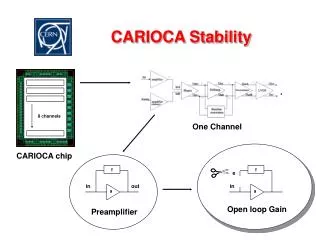
CARIOCA Block Diagram Preamp Signal tail cancellation 2x pole/zero, t0=1.5ns, topology from ASDQ Preamp tail cancellation 1x pole/zero, topology from ATLAS MDT Topology from ATLAS MDT LVDS, standard cell topology from ATLAS MDT prototype Werner Riegler CERN, November 2003
Manpower Walter continues in Cagliari Werner Riegler CERN, November 2003
Submissions Werner Riegler CERN, November 2003
CARIOCA • We had a very useful review in February • We got very useful suggestions in order to increase stability (coupling). • Francis Anghinolfi got involved in order to help us ironing out some of the problems in the preamp. Werner Riegler CERN, November 2003
CARIOCA10 • We received CARIOCA10 on September 15th. • Test board designed by Davide (Cagliari) and produced at CERN. • 17 CARIOCA boards were equipped 34 chips. • Tests were started October 1st. • All test results can be found on http://home.cern.ch/riegler Werner Riegler CERN, November 2003
CARIOCA10 • 8 channels • pos/neg switch • Test pulse even/odd • 8 individual thresholds • Can be switched to a single threshold • Analog output of channel 8 Werner Riegler CERN, November 2003
CARIOCA10 3x4mm chip 82 pins 25 pins on each side Werner Riegler CERN, November 2003
CARIOCA10 • Traditionally one does extensive LAB tests before putting the chip on the chamber. • Because our last testbeam period in T11 was October 22nd to Nov 11th , lab test are not yet finished … • There is no way we could have advanced further up to now … • CARIOCA10 was tested on M3R3 (4boards), GEM (6 boards) and we fully equipped a CERN M3R1 chamber. • We found a nice way for high rate tests in GIF without having beam – this is also ongoing. • Results are preliminary Werner Riegler CERN, November 2003
CARIOCA10 test board • We wanted the results quickly, • we don’t have the final package • We did an ‘optimum’ and ‘worst case’ package: • Optimum Package (‘no package’): • Chip bulk is glued to the board • gound with conductive Epoxi, • Wire bonds are very short • Worst Case Package: • Chip bulk is insulated from the board • gound • Wire bonds are very long Werner Riegler CERN, November 2003
Sensitivity (discriminator) On CARIOCA10, sensitivity was doubled in order to decrease minumum detectable charge (4fC2fC) for GEM application. Maximum threshold is 300mV (limited by discriminator). Sensitivity decreases by factor 2 from 0 to 220pF. Werner Riegler CERN, November 2003
Sensitivity variations Werner Riegler CERN, November 2003 Channel to channel variations are smaller than chip to chip variations
Sensitivity Variations, 0pF Pos: 16.0mV/fC, 0.56mV/fC r.m.s, i.e. 3.54%. Pos: 14.5mV/fC, 0.62mV/fC r.m.s, i.e. 4.31% ‘package’ causes a decrease of 9% Neg: 14.7mV/fC , 0.56mV/fC r.m.s., i.e. 3.8% Neg: 13.1mV/fC, 0.56mV/fC i.e. 4.3% ‘package’ causes a decrease of 11%. Werner Riegler CERN, November 2003
Sensitivity Variations,0pF Subtracting average per chip and scaling by Sqrt(8/7) Pos: 16.0mV/fC, 0.34mV/fC r.m.s, i.e. 2.15%. Pos: 14.5mV/fC, 0.34mV/fC r.m.s, i.e. 2.36% Neg: 14.7mV/fC , 0.40mV/fC r.m.s., i.e. 2.7% Neg: 13.1mV/fC, 0.26mV/fC i.e. 2.0% Werner Riegler CERN, November 2003
Sensitivity Variations Sensitivity is 16(14.7) mV/fC for the positive (negative) amplifier. Sensitivity variations are <5% r.m.s. The DIALOG DACs have 2.44mV LSB I.e. 0.16 fC @ 0pF and 0.32 fC @ 220pF Werner Riegler CERN, November 2003
Extrapol. Minumum Detectable Charge 2.4 fC, 0.37 fC r.m.s. 2.4 fC, 0.24fC r.m.s Minumum detectable charge is correlated with the sensitivity, I.e. the reason for this Limit is a minimum voltage pulse at the Discriminator input in order to make it fire. Werner Riegler CERN, November 2003
Offsets • Offsets were measured on 272 channels by recording the threshold value that inverts the discriminator output. • One DTV sets the threshold for all 8 channels. Werner Riegler CERN, November 2003
Offsets Channel to channel variations are smaller than chip to chip variations Werner Riegler CERN, November 2003
Offsets 795.6mV, 9.9mV r.m.s. The threshold DACs on the DIALOG chip have a range of 625mV to 1250mV in 8 bits i.e. bins of 2.44mV. This is perfectly compatible with this kind of offset spread. Werner Riegler CERN, November 2003
Offsets Subtracting the average offset for each chip and multiplying by sqrt(8/7) gives an rms of 4.54mV. This is the ‘true’ channel to channel variation. It corresponds to 0.3fC at 0pF and 0.6fC at 220pF Werner Riegler CERN, November 2003
The DTV applies the differential threshold voltage to the discriminator. Werner Riegler CERN, November 2003
DTV itself has an offset of about 7.5mV r.m.s Werner Riegler CERN, November 2003
Werner Riegler CERN, November 2003
Offsets+Sensitivity • The channel to channel variation of the sensitivity is <5%. • The channel to channel offset variation is around 5mV r.m.s. • Together with the DTV the channel to channel offset variation is 10mV r.m.s. • Both variations become ‘irrelevant’ when we use individual thresholds. Werner Riegler CERN, November 2003
Noise Neg: 2240+42e-/pF At 0/100/200pF we can use Pos: 1880+45e-/pF threshold of 1.5/5/10 fC. Werner Riegler CERN, November 2003
Power Consumption Power consumption is 43.3/46.6 mW/channel for the positive/negative amplifier. On on board (16 channels) the CARIOCA consumes 0.75W. +DIALOG +Voltage drop from regulator …. Werner Riegler CERN, November 2003
Chamber Test in T11 • M3R1 module 1 chamber (double cathode readout) • Uniformity of this chamber was measured with CARIOCA9 for the CERN PRR. • Crosstalk for single/double cathode readout was evaluated for this chamber with CARIOCA9. Werner Riegler CERN, November 2003
N3 N4 N5 N6 N7 N8 S1S2, no package S3S4, package Beam goes into the drawing 4,13 3,14 2,15 1,16 8,9 7,106,115,12 8,9 7,10 6,11 5,12 4,13 3,142,15 1,16 P9 P10 P11 P12 P14 P16 P13 P15 4,13 3,14 2,15 1,16 8,9 7,106,115,12 8,9 7,10 6,11 5,12 4,13 3,142,15 1,16 1,16 2,15 3,14 4,13 5,12 6,117,108,9 5,12 6,11 7,10 8,9 1,16 2,153,14 4,13 master test 1,16 2,15 3,14 4,13 5,12 6,117,108,9 5,12 6,11 7,10 8,9 1,16 2,153,14 4,13 Gas HV Werner Riegler CERN, November 2003
Chamber test in T11 Werner Riegler CERN, November 2003
Chamber test T11 Dialog -1 Werner Riegler CERN, November 2003
Chamber test T11 Offsets are corrected by 194 individual thresholds. This will finally be done by DIALOG … Werner Riegler CERN, November 2003
Chamber test T11 All outputs were connected to the LVDS-ECL converter with our ‘final’ shielded twisted pair cables. Werner Riegler CERN, November 2003
Chamber Test in T11 • We used 45mV threshold (6-7fC) on all 196 channels. • All channels had <50Hz dark count rate. • Excellent stability ‘without’ dummy capacitor and without shielding ! Werner Riegler CERN, November 2003
Symmetric Termination Due to the large detector capacitance the frontend is extremely sensitive to ground noise (Cdet=100pF, 50V fires the 5fC threshold). With symmetric termination the chip becomes ‘immune’ to this effect. Penalty: larger noise ! ‘Up to CARIOCA8’ we needed this dummy capacitor since the discriminator firing was causing a large pulse on the chip ground. For CARIOCA9/10, many measures were taken in order to reduce this coupling, especially disconnection of substrate contacts in transistors of the digital part. With the final prototype things work perfectly fine without the dummy capacitor, but we still have this option ! Werner Riegler CERN, November 2003
45mV threshold on all Pads - Cathode Pad numbers: Capacitance 112 108 98 88 Threshold 7.6,7.4 6.9,7.0 6.7,6.6 5.9,6.2 fC 7.3,6.6 7.3,6.2 6.6,6.8 6.5,6.5 fC Noise 1.3,1.3 1.3,1.2 1.1,1.3 0.6,1.1 fC 1.3,1.3 1.3,1.1 1.1,1.1 1.1,1.2 fC HV Werner Riegler CERN, November 2003
45mV threshold on all pads: wire pad numbers Wire Pad Capacitances 26.5-28.5pF Thresholds 6.2, 7.4 fC Noise 0.67, 0.69 fC HV Werner Riegler CERN, November 2003
Cathode Efficiency 95% 2.42kV 99% 2.54kV 95% 2.45kV 99% 2.56kV Werner Riegler CERN, November 2003
Wire Efficiency 95% 2.43kV 99% 2.55kV 95% 2.4kV 99% 2.5kV Werner Riegler CERN, November 2003
Detector Capacitance • The cathode pad capacitance in the entire muon system will not exceed 120pF, so with the M3R1 chamber we have already tested the largest cathode capacitances ! • We will however have wire pad chambers with capacitance up to 220 pF (R4) while the M3R1 chamber has only 30pF wire pad capacitances. • Since we don’t have a wire pad chamber we measured the efficiency by adding capacitors to the wire pad. Werner Riegler CERN, November 2003
On Chamber Wire pad Noise packaged and non packaged chip Werner Riegler CERN, November 2003
Wire Pad Efficiency for different Capacitances nonpackage side package side Werner Riegler CERN, November 2003
Efficiency • 2.5kV is a good working point that gives >95% efficiency on the double gap (>99% on the quad gap). • 2.65kV is a good working point that gives >99% efficiency on the double gap. Werner Riegler CERN, November 2003
Crosstalk Crosstalk: Probability of firing the Neighboring pad (infinite time window) Plot presented at the PRR: Measured with CARIOCA9 on the M1R3 Prototype on Pad Position P9,7/10. We decided to use doubel cathode readout since we can survive with 10% crosstalk. In M2M3R1R2 the trigger granularity is given by the wire pads, not the cathode Pads. Crosstalk ‘only’ increases the rate. Werner Riegler CERN, November 2003
Crosstalk CARIOCA9, single, thr 4.7fC, position P9,7/10 CARIOCA9, double, thr 6.8fC, positionP9, 7/10 CARIOCA10, double, thr 7fC, position P11,7/10,no package (S1S2) CARIOCA10, double, thr 7fC, position P11, 7/10, package (S3S4) CARIOCA10, double, thr7fC, position P13, 3/14, no package CARIOCA10, double, thr 6.7fC,position P13,3/14,package (S3S4) ?????????????? Werner Riegler CERN, November 2003
Crosstalk The preamp input stage was actually changed for CARIOCA10 in order to improve the signal tail at large capacitances (phase margin). The design value was 50 since from simulations we know that this is a good value (ASDQ++ used 25 ). Werner Riegler CERN, November 2003
Crosstalk Fraction • Injecting a delta signal in one pad finds a signal on a neighbour pad. • We call the ratio of the two pulse heights the crosstalk fraction. Werner Riegler CERN, November 2003
Crosstalk Fraction 1.7% 1.4%1.5% 1.8% 1.5% 1.4% 1.7% 1.5%1.4% 1.7% 1.5% 1.4% CARIOCA9 CARIOCA10 2.1% 1.7%1.6% 2.2% 1.6% 1.7% 2.2% 1.6%1.6% 2.1% 1.6% 1.7% HV Werner Riegler CERN, November 2003
Crosstalk Fraction • The crosstalk fraction of the M3R1 chamber using CARIOCA10 is 1.6-2.2%. • It is 10-30% larger than for CARIOCA9. • This is a small increase and the 2.2% crosstalk fraction is well within our specifications. • Some time ago we found that we have >95% efficiency if our threshold is at <30% of the average signal and >99% efficiency of our threshold is <20% of the average signal (1.5mm pitch). • With a crosstalk fraction of 20% and 2.2% crosstalk fraction there is no way to have such a large crosstalk ! Werner Riegler CERN, November 2003