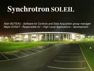
SOLEIL Synchrotron
COMMISSIONING & OPERATION OF SOLEIL. J.C. Besson, J.F. Lamarre, A. Bence, X. Deletoille, Y. Denis, S. Petit, R. Cuoq, P. Da Silva, D. Pereira, G. Roux, Synchrotron Soleil, St Aubin, France. SOLEIL Synchrotron. Summary. 1) Installation and Commissionning. 2) The Control Room.

SOLEIL Synchrotron
E N D
Presentation Transcript
COMMISSIONING & OPERATION OF SOLEIL.J.C. Besson, J.F. Lamarre, A. Bence, X. Deletoille, Y. Denis, S. Petit, R. Cuoq, P. Da Silva, D. Pereira, G. Roux, Synchrotron Soleil, St Aubin, France.
Summary 1) Installation and Commissionning 2) The Control Room 3) Software and Hardware Architecture 4) Some Software Applications 5) Balance-Sheet 6) Conclusion
Installation Accelerators SOLEIL is a third generation Synchrotron radiation Source, located at the Plateau de Saclay near Paris. The 354 m circumference storage ring is mainly composed of 32 (+1) dipoles, 160 quadrupoles, 120 sextupoles, 2 RF cryomodules, ~ 200 vacuum chambers, 6 injection equipments; 12 beamline front-ends and 4 insertion devices (initially). The 157 m circumference Booster comprises 36 dipoles, 44 quadrupoles, 28 sextupoles, 1 RF cavity and 8 injection/extraction equipment Storage Ring Sextupoles (220/280 Kg) Linac Quadrupoles (900/1200 Kg) Dipoles (3,5T) Long Girder (4,8m–7,8T) Booster Cell with 3 girders
1st beam in the Linac on July 2nd,2005 1st beam in the Booster at 110 MeV on July 23rd 2005 Booster : 1st beam accelerated to 2.75 GeV on October 13th 2005 Booster : 1st extraction of 2.75 GeV beam on May 6th, 2006 1st turn in the storage ring on May 14th, 2006 Installation Accelerators General Planning
A commissioning team of about 20 persons composed of the machine physics group and people coming from different areas was constituted in the early stage. They shared their experience and their knowledge in the preparation of the different phases of the commissioning and in the analysis of the results. This organization allowed a fast progress of the commissioning (round clock operation) and different ways to see and solve the encountered problems. Commissioning organization
Commissioning organization • General planning • Detailed protocol for each session • Electronic logbook • One report of each session • A commissioning team • People working 3 x 8h; 7d/7; (example : 7h am-3h pm-11h pm-7h am) • Overlap of 1/2 an hour between 2 successive team • On-call and shift people. • weekly meeting for commissioning team and for each encountered problem
Commissioning team The team: at less one representative from each sudivision Power supply group J. M. Filhol M. P. Level P. Brunelle M. A. Tordeux A. Loulergue A. Madur A. Nadji L. Nadolski R. Nagaoka B. Pottin J. C. Besson J. F. Lamarre J. C. Denard L. Cassinari M. E. Couprie P. Marchand P. Lebasque Diagnostics Group Elect. Control & Acquisition Group operation Group Magnets & insertions Group Inf. Control & Acquisition Group Facilities Group Linac Group RF Group Security Group Vacuum Group
Commissioning Milestones in 2006 14/5 First turn 04/6 Firststored beam 04/6 Firstbeamaccumulation :8.35mA 04/7100mA achieved 10/75 A.h beam dose Shutdown 11/7 – 4/09 13/9First photons to a beamline (DIFFABS) 16/9200mA 21/9First photons to a beamline (TEMPO) 25/9300mA achieved ; 30A.h 29/9U20 at 5.5mm gap 21/9First photons to a beamline (ODE) 15/10 Beam lifetime =8h@100mAin 312 bunches 12/12 First photons to a beamline (SAMBA) 13/12 First photons to a beamline (DESIRS) 21/12 70 A.hbeam dose 21/12 Beam lifetime =10h@100mAin 312 bunches 10 effective weeks
First turns (May 14, 2006) successive turns detected by the FCT successive turns detected by the FCT • Quadrupoles and CorrectorsON, Sextupoles and RFOFF. After correction of first turn trajectory and closing the first turn. • SextupolesON and RF OFF.
10 mm vertical aperture chambers When the beam could be circulated for the first time in the Storage Ringit goes several times through the 10 mm small vertical aperture of the 10 insertion device chambers distributed along the ring without any correction.
Closed Orbit with All correctors OFF H rms=3.1mm max=6.40mm V rms=0.41mm max=1.44mm => Excellent magnet alignment (BPM offsets included after BBA)
Current and Integrated Dose, year 2006 maximum current of 300mA possible with only one cryomodule RF was reached after only 30A.h of integrated current dose
Beam position stability (with SOFB) on 2 straight sections during a 8 hours beamline shift. DX ~ 3 µm , DZ ~ 1 µm mA mm injection Beam current (Source point Positions) X (PX1) X (CASSIOPEE) Z (PX1) Z (CASSIOPEE)
We had no problems with innovations This good result clearly demonstrates the beneficial effect of the NEG coating on the aluminium chamber. This technology was never seen before on accelerators at such extensive use. 2 other innovations concern the RF system: the dedicated Superconducting cavities (1st cryomodule enable alone operation up to 300 mA, a 2nd cryomodule which is being build by ACCEL will enable to reach 500 mA) and the solid state RF amplifiers that are used for the first time in the world for such high power. Except few transistor failures, the system is very stable. Specific and innovative electromagnetic insertion devices were developed for VUV beamlines: 3 HU256 (10eV to 1000eV) 3.6 meter long 1 HU640 (5eV to 40eV) 10 meter long Extended spectral range :from UV (5 eV) up to hard X-Rays (15 KeV) Results and innovations
RF System Innovations Solid State RF Amplifiers4 x 190 kW power amplifiers 1st cryomodule inside SR tunnel Each of the four cavities is powered by a 190 kW solid state amplifier consisting in a combination of four “towers” producing about 50 kW each.
During the shifts, within the operation group, 8 operators take their turns every 8 hours in order to ensure the presence of one of them 24h/24h and 7 days a week in the control room. This operator is assisted by 1 or 2 part-time operators (like ESRF) who come for majority from SOLEIL source division. Before being ready to work in control room, they get training by the "machine physicists" on the general operation of the machine. During shutdown, permanence in control room is ensured by an operator during the normal schedule. Apart from the operation of the machine, the operators are implied in the result analysis and in the developments (software and equipment) enabling a better understanding and operation of the installation. Operation organization
Formation of the operation group According to their arrival Operators were involved in the machines installation and the supervision applications development Staff Number
Control room Organization BOOSTER/TL2 TL1 SR light monitor SR beam size measurement Pinhole camera TUNE Measurement
Control Room Organization Storage Ring FCT BOOSTER to TL2 FCT Linac & TL1 Machine Status TL2 to Storage Ring TL1 to BOOSTER
Control Room Organization Beam Orbit
Hardware architecture Supervision/Control CONTROL BOX
Software architecture 3 major tools used Graphic User Interface generic applications Machine Physics MATLAB, IGOR, python, Labview Monitoring Configuration Globalscreen Archiving binding binding JIVE DEV TREE TDB - HDB TANGO software bus Devices TANGO Flow meter Fault NO Fault Device Device Equipments Motors Magnet power supplies
ELOG (ELectronic LogBooks) Making an entry for single event Attachement File
Extracted data from ELOG in Operator JAVA Program Compilation (MTBF, breakdowns,…) Extraction results in Excel Acquisition data Post processing
Automatic Excel file creation Accelerator physics time Mixed time Beam lines time Health physics time Sharing out of the effective beam time = 558h24 About the whole run 4-2007 From 2007, May the 25th to 2007, Jun the 20th Breakdowns total time = 171h01 About the whole run 4-2007 From 2007, May the 25th to 2007, Jun the 20th
Number of lines that take beam per day, during 4th Run of 2007 Eventually: 25 Beamlines 5 to 8 lines used the beam of photons regularly
Balance - sheet In year 2007, From January to July, 93.8% of the 1426 total hours of beam were delivered to beam lines In year 2006, over the 2084 operating hours The availability of the beam represented 83.5 % of total time, with 11.2 % of time of breakdowns and 5.3 % of time of injection, preparation of manipulations, or interventions
Planned Objectives L 3096 hours Beam Lines 3 000 hours Beam Lines M 1800 hours Machine 1 000 hours Machine . 3864 hours Shutdown L M planned of operation of the year 2007
The SOLEIL accelerator complex is now fully operational. The transition from the commissioning phase to the operation phase went smoothly, thanks to: The strong implication and participation of the operation group during the commissioning of the machine. Significant efforts from the machine physics groups and from the different groups in charge of equipment to transfer their knowledge to the operation crew. The machine availability already reached 93.8 % over the 1521 hours of beam time delivered to the beamlines during the first 7 months of 2007. We are now aiming at increasing further this availability. The next objectives set-up for 2008 are: 500mA operation (with second cryomodule) Preparation for top-up operation Single bunch and 8 bunches operation Secure beam stability with many insertion devices Increase beam availability. CONCLUSION ANDMAIN OBJECTIVES FOR EARLY 2008
Operator’s Team Operation manager Engineer