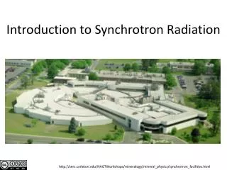
Introduction to Synchrotron Radiation: Properties and Applications
700 likes | 736 Vues
Understand key features of synchrotron radiation, from electromagnetic emission to accelerator dynamics, for advanced research. Discover how synchrotron light sources enhance experiments with high flux, brilliance, and stability. Explore the evolution of synchrotron sources and current challenges in accelerator physics and technology. Learn about storage ring components, insertion devices, and the fascinating world of synchrotron radiation in this comprehensive guide.

Introduction to Synchrotron Radiation: Properties and Applications
E N D
Presentation Transcript
Synchrotron radiation R. Bartolini John Adams Institute for Accelerator Science, University of Oxford and Diamond Light Source JUAS 2014 27-31 January 2014
Contents Introduction to synchrotron radiation properties of synchrotron radiation synchrotron light sources angular distribution of power radiated by accelerated particles angular and frequency distribution of energy radiated radiation from undulators and wigglers Storage ring light sources electron beam dynamics in storage rings radiation damping and radiation excitation emittance and brilliance low emittance lattices diffraction limited storage rings
What is synchrotron radiation The electromagnetic radiation emitted when the charged particles are accelerated radially (v a) is called synchrotron radiation It is produced in the synchrotron radiation sources using bending magnets undulators and wigglers Electromagnetic radiation is emitted by charged particles when accelerated
Broad Spectrum which covers from microwaves to hard X-rays: the user can select the wavelength required for experiment; either with a monochromator or adjusting the emission wavelength of insertion devices Synchrotron radiation sources properties (I) synchrotron light
High Flux: high intensity photon beam, allows rapid experiments or use of weakly scattering crystals; High Brilliance (Spectral Brightness): highly collimated photon beam generated by a small divergence and small size source Polarisation: both linear and circular (with IDs) Pulsed Time Structure: pulsed length down to High Stability: submicron source stability in SR … and it can be computed! Flux = Photons / ( s BW) Synchrotron radiation sources properties (II) Partial coherence in SRs Full T coherence in FELs Brilliance = Photons / ( s mm2 mrad2 BW ) 10s ps in SRs 10s fs in FELs
X-ray tube 60W bulb Candle diamond X-rays from Diamond will be 1012 times brighter than from an X-ray tube, 105 times brighter than the SRS ! Peak Brilliance
X-ray sources Courtesy K. Wille
Electrons are generated and accelerated in a linac, further accelerated to the required energy in a booster and injected and stored in the storage ring Layout of a synchrotron radiation source (I) The circulating electrons emit an intense beam of synchrotron radiation which is sent down the beamline
Evolution of synchrotron radiation sources (I) • First observation: • 1947, General Electric, 70 MeV synchrotron • First user experiments: • 1956, Cornell, 320 MeV synchrotron • 1st generation light sources: machine built for High Energy Physics or other purposes used parasitically for synchrotron radiation • 2nd generation light sources: purpose built synchrotron light sources, SRS at Daresbury was the first dedicated machine (1981 – 2008) • 3rd generation light sources: optimised for high brilliance with low emittance and Insertion Devices; ESRF, Diamond, …
Evolution of synchrotron radiation sources (II) • 4th generation light sources: photoinjectors LINAC based Free Electron Laser sources; • FLASH (DESY) 2007 • LCLS (SLAC) 2009 • SACLA (Japan) 2011 • Elettra (Italy) 2012 • and in the near(?) future • 4th generation light sources storage ring based: diffraction limited storage rings • …and even a 5th generationwith more compact and advanced accelerator technologies e.g. based on laser plasma wakefield accelerators
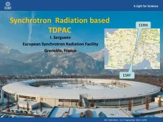
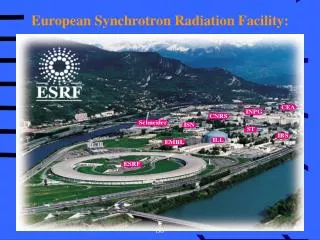
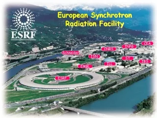
ESRF SSRF 3rd generation storage ring light sources 1992ESRF, France (EU) 6 GeV ALS, US 1.5-1.9 GeV 1993 TLS, Taiwan 1.5 GeV 1994ELETTRA, Italy 2.4 GeV PLS, Korea 2 GeV MAX II, Sweden 1.5 GeV 1996APS, US 7 GeV LNLS, Brazil 1.35 GeV 1997 Spring-8, Japan 8 GeV 1998BESSY II, Germany 1.9 GeV 2000ANKA, Germany 2.5 GeV SLS, Switzerland 2.4 GeV 2004SPEAR3, US 3 GeV CLS, Canada 2.9 GeV 2006: SOLEIL, France 2.8 GeV DIAMOND, UK 3 GeV ASP, Australia 3 GeV MAX III, Sweden 700 MeV Indus-II, India 2.5 GeV 2008SSRF, China3.4 GeV 2009PETRA-III, Germany 6 GeV 2011ALBA, Spain3 GeV
3rd generation storage ring light sources under construction or planned NLSL-II > 2013NSLS-II, US 3 GeV MAX-IV, Sweden 1.5-3 GeV SOLARIS, Poland 1.5 GeV SESAME, Jordan 2.5 GeV TPS, Taiwan3 GeV CANDLE, Armenia 3 GeV PEP-X, USA 4.5 GeV Spring8-II, Japan 6 GeV Max-IV R. Bartolini, JUAS, 27-31 January 2014 13/71
Oct 2006 Diamond aerial views June 2003
Main components of a storage ring Dipole magnets to bend the electrons Quadrupole magnets to focus the electrons Sextupole magnets to focus off-energy electrons (mainly) RF cavities to replace energy losses due to the emission of synchrotron radiation
Main components of a storage ring Insertion devices (undulators) to generate high brilliance radiation Insertion devices (wiggler) to reach high photon energies R. Bartolini, JUAS, 27-31 January 2014 16/71
Accelerator physics and technology challenges Photon energy Brilliance Flux Stability Polarisation Time structure Ring energy Small Emittance Insertion Devices High Current; Feedbacks Vibrations; Orbit Feedbacks; Top-Up Short bunches; Short pulses R. Bartolini, JUAS, 27-31 January 2014 17/71
Brilliance and low emittance The brilliance of the photon beam is determined (mostly) by the electron beam emittance that defines the source size and divergence
Brilliance with IDs Thanks to the progress with IDs technology storage ring light sources can cover a photon range from few tens of eV to tens 10 keV or more with high brilliance Medium energy storage rings with In-vacuum undulators operated at low gaps (e.g. 5-7 mm) can reach 10 keV with a brilliance of 1020 ph/s/0.1%BW/mm2/mrad2 R. Bartolini, JUAS, 27-31 January 2014 19/71
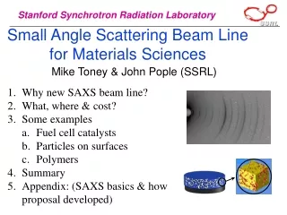
photo-emission (electrons) electronic structure & imaging EXAFS XRF imaging fluorescence Many ways to use x-rays crystallography & imaging diffraction scattering SAXS & imaging absorption Spectroscopy EXAFS XANES & imaging from the synchrotron to the detector R. Bartolini, JUAS, 27-31 January 2014 20/71
Medicine, Biology, Chemistry, Material Science, Environmental Science and more Biology Archeology Reconstruction of the 3D structure of a nucleosome with a resolution of 0.2 nm A synchrotron X-ray beam at the SSRL facility illuminated an obscured work erased, written over and even painted over of the ancient mathematical genius Archimedes, born 287 B.C. in Sicily. Applications X-ray fluorescence imaging revealed the hidden text by revealing the iron contained in the ink used by a 10th century scribe. This x-ray image shows the lower left corner of the page. The collection of precise information on the molecular structure of chromosomes and their components can improve the knowledge of how the genetic code of DNA is maintained and reproduced R. Bartolini, JUAS, 27-31 January 2014 21/71
Franklin and Gosling used a X-ray tube: Brilliance was 108 (ph/sec/mm2/mrad2/0.1BW) Exposure times of 1 day were typical (105 sec) e.g. Diamond provides a brilliance of 1020 100 ns exposure would be sufficient Life science examples: DNA and myoglobin Nowadays pump probe experiment in life science are performed using 100 ps pulses from storage ring light sources: e.g. ESRF myoglobin in action Photograph 51 Franklin-Gosling DNA (form B) 1952
The general solutions for the wave equation driven by a time varying charge and current density read (in the Lorentz gauge) Lienard-Wiechert potentials (II) (see next slide) where ret means retarted Using the properties of the Dirac deltas we can integrate and obtain the Lienard-Wiechert potentials These are the potentials of the em fields generated by the charged particle in motion. The trajectory itself is determined by external electric and magnetic fields R. Bartolini, JUAS, 27-31 January 2014 23/71
[ ]ret means computed at time t’ Lienard-Wiechert Potentials (III) Potentials and fields at position x at time t are determined by the characteristic of the electron motion at a time t’ t’ – t is the time it takes for the em radiation to travel the distance R(t’) i.e. grey is the position of the electron at time t R. Bartolini, JUAS, 27-31 January 2014 24/71
The Lienard-Wiechert fields and are called Lienard-Wiechert fields The computation has to be done carefully since the potentials depend on t’, not t. The factor dt/dt’ represents the Doppler factor. We get The electric and magnetic fields are computed from the potentials using velocity field acceleration field If we consider the acceleration field we have and the correct dependence as 1/R as for radiation field R. Bartolini, JUAS, 27-31 January 2014 25/71
Power radiated by a particle on a surface is the flux of the Poynting vector Power radiated Angular distribution of radiated power radiation emitted by the particle We will analyse two cases: acceleration orthogonal to the velocity → synchrotron radiation acceleration parallel to the velocity → bremmstrahlung R. Bartolini, JUAS, 27-31 January 2014 26/71
Synchrotron radiation: non relativistic motion (I) Assuming and substituting the acceleration field The angular distribution of the power radiated is given by Working out the double cross product We have R. Bartolini, JUAS, 27-31 January 2014 27/71
Synchrotron radiation: non relativistic motion (II) Since where is the angle between the acceleration and the observation direction, we finally get The angular distribution of power reads R. Bartolini, JUAS, 27-31 January 2014 28/71
Synchrotron radiation: non relativistic motion (III) This integral gives Larmor’s formula It shows that radiation is emitted when the particle is accelerated. Using Integrating over the angles gives the total radiated power we have (to be used later for the generalisation to the relativistic case) R. Bartolini, JUAS, 27-31 January 2014 29/71
Synchrotron radiation: relativistic motion (I) In the relativistic case the total radiated power is computed in the same way. Using only the acceleration field (large R) The angular distribution of the power emitted is (use the retarted time!) The emission is peaked in the direction of the velocity The pattern depends on the details of velocity and acceleration but it is dominated by the denominator R. Bartolini, JUAS, 27-31 January 2014 30/71
and substituting the acceleration field velocity acceleration: synchrotron radiation (I) Assuming cone aperture 1/ When the electron velocity approaches the speed of light, the emission pattern is sharply collimated forward R. Bartolini, JUAS, 27-31 January 2014 31/71
velocity acceleration: synchrotron radiation (II) Courtesy K. Wille R. Bartolini, JUAS, 27-31 January 2014 32/71
Integrating over the whole solid angle we obtain the total instantaneous power radiated by one electron Total radiated power via synchrotron radiation • Strong dependence 1/m4 on the rest mass • proportional to 1/2 ( is the bending radius) • proportional to B2 (B is the magnetic field of the bending dipole) The radiation power emitted by an electron beam in a storage ring is very high. The surface of the vacuum chamber hit by synchrotron radiation must be cooled. R. Bartolini, JUAS, 27-31 January 2014 33/71
and substituting the acceleration field velocity || acceleration: bremsstrahlung Assuming Integrating over the angles as before gives the total radiated power R. Bartolini, JUAS, 27-31 January 2014 34/71
Relativistic generalization of Larmor’s formula Comparison of radiation from linear and circular trajectories The total radiated power can also be computed by relativistic transformation of the 4-acceleration in Larmor’s formula with and Back to the general expression for the acceleration field, integrating over the angles gives the total radiated power We build the relativistic invariant R. Bartolini, JUAS, 27-31 January 2014 35/71
The particle energy is Comparison of radiation from linear and circular trajectories Therefore and Inserting in the formula we get For a linear trajectory R. Bartolini, JUAS, 27-31 January 2014 36/71
Repeating for a circular trajectory Comparison of radiation from linear and circular trajectories The particle energy is now constant Therefore Inserting in the formula we get the total radiated power in a circular trajectory This is 2 larger than the linear case P(v || a) 1/2P(v a) R. Bartolini, JUAS, 27-31 January 2014 37/71
In the time Tb spent in the bendings the particle loses the energy U0 Energy loss via synchrotron radiation emission in a storage ring i.e. Energy Loss per turn (per electron) Power radiated by a beam of average current Ib: this power loss has to be compensated by the RF system Power radiated by a beam of average current Ib in a dipole of length L (energy loss per second) R. Bartolini, JUAS, 27-31 January 2014 38/71
The energy received by an observer (per unit solid angle at the source) is The radiation integral (I) Using the Fourier Transform we move to the frequency space Angular and frequency distribution of the energy received by an observer Neglecting the velocity fields and assuming the observer in the far field: n constant, R constant Radiation Integral R. Bartolini, JUAS, 27-31 January 2014 39/71
The radiation integral can be simplified to [see Jackson] The radiation integral (II) How to solve it? • determine the particle motion • compute the cross products and the phase factor • integrate each component and take the vector square modulus Calculations are generally quite lengthy: even for simple cases as for the radiation emitted by an electron in a bending magnet they require Airy integrals or the modified Bessel functions (available in MATLAB) R. Bartolini, JUAS, 27-31 January 2014 40/71
Radiation integral for synchrotron radiation In the limit of small angles we compute Trajectory of the arc of circumference [see Jackson] Substituting into the radiation integral and introducing R. Bartolini, JUAS, 27-31 January 2014 41/71
Using the properties of the modified Bessel function we observe that the radiation intensity is negligible for >> 1 Critical frequency and critical angle Higher frequencies have smaller critical angle Critical frequency Critical angle For frequencies much larger than the critical frequency and angles much larger than the critical angle the synchrotron radiation emission is negligible R. Bartolini, JUAS, 27-31 January 2014 42/71
Integrating on all angles we get the frequency distribution of the energy radiated Frequency distribution of radiated energy >> c << c often expressed in terms of the function S() with = /c R. Bartolini, JUAS, 27-31 January 2014 43/71
It is possible to verify that the integral over the frequencies agrees with the previous expression for the total power radiated [Hubner] Frequency distribution of radiated energy The frequency integral extended up to the critical frequency contains half of the total energy radiated, the peak occurs approximately at 0.3c It is also convenient to define the critical photon energy as For electrons, the critical energyin practical units reads 50% 50% R. Bartolini, JUAS, 27-31 January 2014 44/71
Synchrotron radiation is emitted in an arc of circumference with radius , Angle of emission of radiation is 1/ (relativistic argument), therefore transit time in the arc of dipole Heuristic derivation of critical frequency During this time the electron travels a distance The time duration of the radiation pulse seen by the observer is the difference between the time of emission of the photons and the time travelled by the electron in the arc The width of the Fourier transform of the pulse is R. Bartolini, JUAS, 27-31 January 2014 45/71
Polarisation in the orbit plane Polarisation orthogonal to the orbit plane Polarisation of synchrotron radiation In the orbit plane = 0, the polarisation is purely horizontal Integrating on all frequencies we get the angular distribution of the energy radiated Integrating on all the angles we get a polarization on the plan of the orbit 7 times larger than on the plan perpendicular to the orbit R. Bartolini, JUAS, 27-31 January 2014 46/71
Dependence of the frequency distribution of the energy radiated via synchrotron emission on the electron beam energy Synchrotron radiation emission as a function of beam the energy Critical frequency Critical angle No dependence on the energy at longer wavelengths Critical energy R. Bartolini, JUAS, 27-31 January 2014 47/71
Brilliance with IDs (medium energy light sources) Brilliance dependence with current with energy with emittance Medium energy storage rings with in-vacuum undulators operated at low gaps (e.g. 5-7 mm) can reach 10 keV with a brilliance of 1020 ph/s/0.1%BW/mm2/mrad2 R. Bartolini, JUAS, 27-31 January 2014 48/71
Radiation emitted by undulators and wigglers Types of undulators and wigglers Radiation from undulators and wigglers R. Bartolini, JUAS, 27-31 January 2014 49/71
Periodic array of magnetic poles providing a sinusoidal magnetic field on axis: Undulators and wigglers Solution of equation of motions: Undulator parameter Constructive interference of radiation emitted at different poles R. Bartolini, JUAS, 27-31 January 2014 50/71