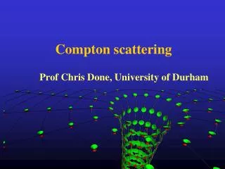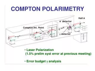
COMPTON POLARIMETRY
COMPTON POLARIMETRY. Analysis status Scaling laws Measurement @ 3 GeV Toward 850 MeV. Overview. e - detector. g detector. Compton Int. Point. Detection. 650 m m strips. Hall A. 7mm gap. PbW04. e - only g only Coincidences. “e - Only”.

COMPTON POLARIMETRY
E N D
Presentation Transcript
COMPTON POLARIMETRY • Analysis status • Scaling laws • Measurement @ 3 GeV • Toward 850 MeV
Overview e- detector g detector Compton Int. Point
Detection 650 mm strips Hall A 7mm gap PbW04 • e- only • g only • Coincidences
“e- Only” • Differential method, Running-time a <A2> • Main systematic error = calibration • Typical 2.5% relat. error @4.5 GeV • Installed online
Response Function Electron detector o g energy tagger 1 strip selected • Response func. over e- det. Range • Semi-integration method • Optimized software threshold • Cross-check of syst.
Error Budget Running conditions: • Ebeam =4.5 GeV • Ibeam = 40 mA • 40 min run • <Ana. Power> = 5.8%
AMax <A> A a k x E <A2> Scaling Laws Error in previous estimates… 0.85 GeV 3.0 GeV 4.5 GeV stot ~ cst Run-time a (s x A2) a (k2 x E2)
Measurement @ 3 GeV • Reduce gap from 7 to 5mm • Covers more than 75% of E range • 1% stat. in 1h • Goal: 2% syst.
Toward 850 MeV Kinematics with IR laser:
e- Detection • Differential method • m-strips of 50 mm for good calibration Green laser I.R. laser -Need to detect e- between 2.5 and 3mm of the primary beam -Could be done with remote position control of the e- detector. -1% stat in 20h -Compton edge 6mm from the primary beam -1% stat in 5h (assuming 1.5kW laser) -Light upgrade of electron det. -Distances from beam currently achieved -Major hardware change Bkg? Beam position stability?
AMax <A> <A2> g detection Integration method with very low threshold (few% of Compton edge) -No syst. from resolution and calibration -Need to know the det. Efficiency -1% stat. in 4.5 days Requirements with IR laser: • Eg = [120 keV-12 MeV] • 100 kHz • High efficiency
g PMT g Detection 2 layers detector: LSO: 0.11 MeV PbWO4, pure CsI: 110 MeV • Huge light yield, 420nm • Dense: 7.4g/cm3 • Fast: 42ns • Size of 4x4x4 cm available • 20 to 200 ge per g • Transparent to 420 nm • 6 to 60 ge per g Main systematics: • Bkg level: can be tested in April during GDH. • Monitoring of efficiency: few % level? radioactive sources, e expected flat above.
CONCLUSION With electron detector 2mm lower: -OK for HAPPEx2 -Error budget tight for 4He Upgrades: -Green laser: 175 k$, 2 man/year Would make e- detect. Work -New photon detector: Can be tested in spring 2003 with current setup