Understanding Interferometers and Radio Astronomy Through Tom Wilson's Lecture Series
This lecture review by Tom Wilson dives into the concepts of interferometers, the Rayleigh-Jeans law, and the behavior of antennas. It covers the technical aspects of receivers, including coherent and non-coherent systems, the significance of atomic physics in radio astronomy, and various forms of electromagnetic radiation. Topics include the behavior of HI clouds, excitation of atomic systems, and the intricacies of radio recombination lines, all situated in the context of observational techniques in radio astronomy. A vital resource for students of astrophysics.

Understanding Interferometers and Radio Astronomy Through Tom Wilson's Lecture Series
E N D
Presentation Transcript
Lecture 4 By Tom Wilson
Review page 1 Interferometers on next page Rayleigh-Jeans: True if h n << kT Sn= measured: if qs < qB, T=TMB qs = qb, T = TS In mm / sub mm usually calibrations give TA* = “corrected antenna temperature” corrected for atmosphere, and telescope efficiency for very extended source TMB: corrected for atmosphere and beam efficiency
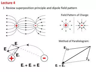
Review page 2 Grading Across the Aperture and Far E Field as limit of interferometer
Review page 3 Above: the 2 antennas on the earth’s surface have a different orientation as a function of time. Below: the ordering of correlated data in (u,v) plane.
Review page 5 RECEIVERS (MM) Mix from sky frequency to IF frequency (4 GHz) and amplify signal 2 LIMITS:
Review page 5 Analog Coherent Receiver Block Diagram Time Frequency=n, f Total Amplification=1016
Review page 6 In centimeters, the first stage of a receiver is a cooled transistor ampifier, a HEMT (InP, GaAs…). For HEMTs, TRX= 2 (nGHz ) with a minimum of 4 K, perhaps. The minimum noise for a coherent receiver is h n / k or about 5 K at 100 GHz. With mixers, the Rx noise is usually Double Sideband (DSB). For spectral lines want Single Sideband (SSB) , where TSSB =2 TDSB. Bolometers- non coherent receivers. Noise quoted in NEP (watts Hz –1/2). For a given system on a telescope, performance is frequently given as “detectable source in Jy in 1 sec”. For HHT and 19 channel bolometer, 1 Jy in 1 sec. SCUBA/JCM this is 4 x better (2 x collecting area, 2 x rx efficiency). SCUBA has 37 beams at 0.87nm. INTERPRETATION Continuum dust thermal emission
Review page 7 Free-Free (Bremstrahlung) Synchrotron emission Radiation frequency is increased by beaming 1/n and doppler 1/n2, so critical Frequency is g=104 for 10 GHz d: energy spectrum of cosmic rays
Lecture4 page 1 • RELATE ATOMIC PHYSICS TO RADIO ASTRONOMY • Einstein A & B coefficients and their role in Equation of radiative transfer • A+B coefficients in a 2 level system. Start with: Nu Aul+Bul Nu U=Blu Nl U U=4p/c In After somemanipulation, get Inserting numerical values of physical constants:
Lecture4 page 2 In terms of column density, Nl, get GROUND STATE OF HYDOGEN HI line from overlap of proton and electron wave functions—see next slide In Q. M., allowed transitions only between wave functions of opposite parity:
S D P F N=1 (From H. E. White, ‘ Introduction to Atomic Physics’ )
Lecture4 page 4 Apply all this to HI: “21 cm line” hyperfine transition n0 = 1.420 405…GHz Aul= 2.87 · 10-15 sec-1 A very non classical system!! Show For HI, h ·n / k = 0.06 K
Lecture4 page 5 Similar transition are for D and 3He+ EXCITATION OF 2 LEVEL SYSTEM Competition of radiation and collisions Answer: hn k For HI, Tex= Tk , if n >1 cm-3
Lecture4 page 6 HI Clouds assumed to be in pressure equilibrium HI: Used to obtain dynamics of galaxies, “HI masses” of galaxies, map rotation curve of our galaxy, … See absorption line if TBG > Tex (HI) = Tk , geometry and cloud size relative to background continuum plays a role - - complex but solvable !
A=2.4 10-6 sec-1 A=2.65 10-7 sec-1 A=7.93 10-8 sec-1 (Use two level excitation with collision rate of 10-10 cm3 sec-1 to get n*)
Lecture4 page 7 RADIO RECOMBINATION LINES These are “Rydberg Atoms” with Principal Quantum Numbers > 20 m = electron mass and M = nucleon mass Set z2 = 1
Lecture4 page 7 e Saha Eq’n Then, line intensity is proportional to NpNe From Bremsstrahlung, so is Tc for HII regions Find
NON-LTE EFFECTS Lecture4 page 9 Nn: Actual population Nn*: LTE population gu and ge are nearly equal for u, l > 20, so Then Tex < 0 population inversion typically Tex= -300K In Lecture 1, if |t| < 0 , get
Lecture4 page 10 If lines are optically thin, what is amplified? On ‘Tools’, p. 342 is: Often lots of algebra ! b< 0 and depends on density, and could be large!
Lecture4 page 11 APPLY TO AN ACTUAL HII REGION (ORION A) At low frequencies core radiation broadened (large n) At high frequencies, cores dominates, but not much maser emission in diffuse foreground gas. Brown, Lockman & Knapp in Annual Reviews (1978) proposed a recombination line theory with large EM, low ne and lots of line masering. This is not matched by measurements. So unrealistic!
Lecture4 page 12 This is where MACROPHYSICS meets MICROPHYSICS Macrophysics: structure of a source on parsec Microphysics: cross sections, local populations of atoms Confluences of these – i.e. masering depends on atomic physics and source structure could be thought of as “Radiative transfer”
Lecture4 page 13 Quantum description: 2S+1LJ