Concept Vehicle Configuration
90 likes | 181 Vues
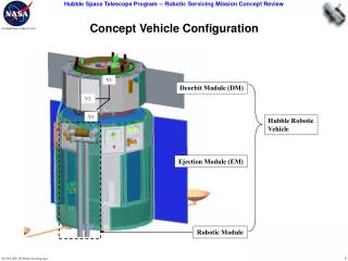
V1. V2. V3. Concept Vehicle Configuration. Deorbit Module (DM). Hubble Robotic Vehicle. Ejection Module (EM). Robotic Module. Conduit Deploy. Deploy Conduit and Latch onto the HST Handrails/Structure

Concept Vehicle Configuration
E N D
Presentation Transcript
V1 V2 V3 Concept Vehicle Configuration Deorbit Module (DM) Hubble Robotic Vehicle Ejection Module (EM) Robotic Module
Conduit Deploy • Deploy Conduit and Latch onto the HST Handrails/Structure • Conduit provides 1553 Bus connection from RSUs attached to WFC3 to 486 Computer located in Bay 1 and electrical connections between HST SA3 Diode Boxes and new batteries
Grapple Arm Task 1: HST Capture/Berthing • Arm Characteristics: • Grapple Arm end effector captures HST Grapple Fixture (GF) • 7 joints, 8” diameter to null differential rates upon capture • Closed loop vision system to track GF target without an operator in event of LOS • Open loop positioning error less than 1.5” and 2 degrees for berthing to HRV • Large end effector capture envelope and high arm tip speed permits: • Relaxed requirement on HRV tracking errors with respect to HST at rendezvous • High confidence of capture even if HST is rolling since arm can track HST
HST Capture Sequence HRV approaches HST and holds at 7m range Arm assumes ‘Ready to Capture’ pose HRV positions HST GF in ‘Capture Box’, arm acquires GF target When position/orientation meets “Ready to Capture” conditions, HRV triggers arm to Capture and turns off thrusters Arm tracks GF target with EE camera and closed loop vision processing/servo’ing EE captures HST GF and brings HST to near rest, brakes applied HRV thrusters enabled and combined vehicle stabilized Approach vector and standoff distance may be selected from a variety of options
EM Equipment Breakdown • Propulsion system • ‘TDRSS’ program Hydrazine tanks (4) • Used for HRV pursuit & docking, and during EM deorbit • Pressurant (‘blow-down’) tanks (2) • Valves, filters, plumbing, regulators, heaters, etc. (not shown) (Note that EM bulkhead at tank mounting flange level blocks view of lower half of tanks)
EM Equipment Breakdown • GN&C system, cont: • IMU’s (2) • Magnetometers (2) • Torquer bars (3) • Mounted along X,Y,& Z axes • Momentum wheels (4) • Mounted in pyramid pattern Mag Torquer bars Several of the listed items are not shown in these views. There is radiator panel mounting space to accommodate all the items listed.
EM Equipment Breakdown • GN&C system: • Horizon sensors (2) • Star trackers / celestial nav (2) • Coarse Sun Sensors (8) • 1 each on fwd & aft ends, 6 distributed around DM-end, on L-brackets facing radially out. • (GPS antennae – also on next slide)
Capture Approach Candidates • Baseline Approach • Point relative navigation sensors at one of the HST grapple fixtures • Most conceptually straightforward approach for a grapple capture • Mismatch in HST/HRV inertia properties result in torque and momentum storage requirements which exceed reaction wheel capabilities • “Sideways” Approach • Make minor HRV axis nominally parallel with HST minor axis • Torque and momentum storage requirements reduced to within reaction wheel capabilities • Requires repackaging of relative navigation sensor suite • Aft End Approach • Applicable to both grapple and direct docking capture methods • Matches HST/HRV minor axes • Avoids potential sources of interference (i.e. HST”s high gain antenna and solar arrays) • Control analysis pending