Download
1 / 25
250 likes | 331 Vues
Explore the goals, features, and challenges of the ST-VNS fusion research facility discussed at the FNST Meeting at UCLA. Discover the scientific and technical drivers shaping the future of fusion energy research.

E N D
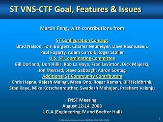
ST VNS-CTF Goal, Features & Issues Martin Peng, with contributions from ST Configuration Concept Brad Nelson, Tom Burgess, Charles Neumeyer, Dave Rasmussen, Paul Fogarty, Adam Carroll, Roger Stoller U.S. ST Coordinating Committee Bill Dorland, Don Hillis, Rob La Haye, Fred Levinton, Dick Majeski, Jon Menard, Steve Sabbagh, Aaron Sontag Additional ST Community Contributors Chris Hegna, Rajesh Maingi, Masa Ono, Roger Raman, Bill Heidbrink, Stan Kaye, Mike Kotschenreuther, Swadesh Mahajan, Prashant Valanju FNST Meeting August 12-14, 2008 UCLA (Engineering IV and Boelter Hall) ST-VNS Goals, Features, Issues, FNST Mtg, UCLA, 8/12-14/08
Topics • Suggested ST program goal for the ITER era • What are the scientific and technical drivers for VNS-CTF? • A broadened testing program to discover, understand and innovate • Enduring features of VNS-CTF • High maintainability via modularity • ST scientific and technical design basis ST-VNS Goals, Features, Issues, FNST Mtg, UCLA, 8/12-14/08
Suggested ST goal for ITER era Long Term ST Mission: To develop compact, high-beta, burning plasma capability for fusion energy ITER - Era Goal (15-20 years): To establish ST knowledge base to construct a low aspect‐ratio fusion component testing facility that provides high heat flux, neutron flux, and duty factor needed to inform the design of demonstration fusion power plant ST-VNS Goals, Features, Issues, FNST Mtg, UCLA, 8/12-14/08
ST goal - continued Address Themes B and C issues defined in a recent FESAC Panel report, using A sustained plasma fusion environment to provide Wall load: ~1 MW/m2 High fluence: ~ an order of magnitude beyond ITER This can be done in parallel with ITER Need high duty factor in a compact volume neutron source (VNS) to enable the required component testing ST-VNS Goals, Features, Issues, FNST Mtg, UCLA, 8/12-14/08
FESAC Report on Opportunities, etc. identified 15 gaps for fusion energy – 9 in engineering and nuclear science and technology 3 Themes: A BC A - Creating predictable high-performance steady - state plasmas: ITER + stellarators + superconducting tokamaks + modeling; plasma control technologies (magnets, plasma heating and current drive, fueling etc.) – likely via international collaborations. B - Taming the plasma-material interface: plasma wall interactions (sputtering, melting etc), plasma facing materials and components (high heat flux, rf antennas etc.) under very high neutron fluence C - Harnessing fusion power: tritium breeding & handling, high grade heat extraction, low activation materials, safety, remote handling ST-VNS Goals, Features, Issues, FNST Mtg, UCLA, 8/12-14/08
Goal is challenging – is it achievable? • Address issues and gaps on Plasma-Material Interface and Fusion Power not addressed otherwise; • Requires a broadened component testing program using high fusion neutron fluence and Demo‐relevant heat fluxes; • Motivates ST R&D and design assessments; • Aims to design and begin construction of an aspect-ratio optimized U.S. component testing facility. • To achieve this goal, the ST program needs to • Work jointly with the tokamak and other science and technology programs; • Use attractive ST features and shared knowledge and challenges of tokamak and enabling technologies; • Identify and resolve key ST scientific and technical questions. ST-VNS Goals, Features, Issues, FNST Mtg, UCLA, 8/12-14/08
A Broadened Program of component testing will enable discovery, understanding, and innovation to bridge the gaps in knowledge DOE Science Community Underlying Science questions; R&D to answer them Performance Models (PMI, heat flux, erosion, corrosion, tritium, production/account.) Informs Testing to Discover, Understand, Innovate Enables Enables Testing on VNS-CTF; hot-cell labs; enabling plasma, materials, engineering, & nuclear science & technology Component Performance Predictions Predictions of Physical Properties Motivates Motivates Diagnostics of Physical Properties Control Tools Component Performance Instrumentation ST-VNS Goals, Features, Issues, FNST Mtg, UCLA, 8/12-14/08 7
The required VNS-CTF pulse duration – key phenomena of interest that have the longest time scales ST-VNS Goals, Features, Issues, FNST Mtg, UCLA, 8/12-14/08
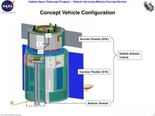
Essential VNS-CTF features are driven by high duty factor, requiring high reliability & maintainability R0 ~ 1.2m • Cu TF magnet post • MIC startup solenoid • Continuous NBI • Super-X divertor • Minimizing disruptions • Extensive modularity • Remote handling • Ex-shield boundary hands-on access • Large design margins • Tradeoffs plus R&D leverage
Single-turn Cu magnet reliability • Conventional multi-turn coil set reliability is problematic and replacement of a TF or PF is extremely difficult. • Failures are usually electrical and S/C coils have high quench voltages (some kVs) • Significant shielding (1+ meters)is required to protect insulation and limit nuclear heating of S/C coils • Single-turn Cu allows much lower voltages (10-15 V) • Issues include: • High current, low voltage power supply system and bus (10 MA vs. 75 kA in ITER) • High current electrical joints/insulation • High current density (resistive heating) • Radiation damage (essentially no shielding) ST-VNS Goals, Features, Issues, FNST Mtg, UCLA, 8/12-14/08
High current power supply and feeder • High current (~ 10 MA) power supplies and feeder bus system expected to be more expensive • To balance multiple supplies, current control and feedback (instead of voltage) is needed • Dissipation in feeds must be minimized – short distance, HTSC? (0.6- GW, 140-kV line in Long Island) • R&D: homopolar generator • Cheaper, works better at low voltage ST-CTF Example Rotor Liquid Metal ST-VNS Goals, Features, Issues, FNST Mtg, UCLA, 8/12-14/08
10-MA electrical joints at end of center core Due to thermal and structural expansion of the center core, sliding joints may be needed. Mechanical sliding joint – standard approach - Average current densities need to be reasonable (<1 kA/cm2), cooling is important Liquid metal joint is intriguing possibility - Need adequate seals - Configure Lorentz (JxB) forces to retain liquid instead of expelling it - Need rigorous prototyping & testing at full parameters ST-VNS Goals, Features, Issues, FNST Mtg, UCLA, 8/12-14/08
Central Cu core cooling and radiation damage • Current density is expected to be high for compact device (5.3 kA/cm2, ~ 150 W/cm3 in Glidcop) • Nuclear heating adds ~20 W/cm3 at surface • Will require careful optimization of cooling passages • Must consider corrosion, radiation hardening • Glidcop life 0.5 MW-a/m2(~5 dpa) measured (fission) • CTF example – 2 calendar year under full performance • R&D: How to build? Life under 14-MeV neutrons? • Ferritic Steel structure life of ~10 dpa, good for 3-4 calendar year under full performance ST-VNS Goals, Features, Issues, FNST Mtg, UCLA, 8/12-14/08
Divertor solutions • Conventional divertor has very high heat (~40 MW/m2, = 0.5 cm) and neutron fluxes • Major ITER R&D (~10 MW/m2) will benefit ST goal • “Super-X” Divertor lowers heat flux by > 5-6x • Expanded SOL area • Longer connection length; increased radiation loss • More nuclear shielding • Another R&D: power & particle control using liquid metal in lower single null ST-VNS Goals, Features, Issues, FNST Mtg, UCLA, 8/12-14/08
High Maintainability via Modularity • Extensive modularity expedites remote handling: • Large components with linear motion • All welds external to shield boundary • Parallel mid-plane/vertical RH operation Centerstack Assembly Upper Blanket Assy Lower Blanket Assy Upper PF coil Upper Diverter Lower Diverter Lower PF coil Upper Piping Electrical Joint Top Hatch Shield Assembly NBI Liner Test Modules Disconnect upper piping Remove sliding electrical joint Remove top hatch Remove upper PF coil Remove upper diverter Remove lower diverter Remove lower PF coil Extract NBI liner Extract test modules Remove upper blanket assembly Remove lower blanket assembly Remove shield assembly Remove centerstack assembly ST-VNS Goals, Features, Issues, FNST Mtg, UCLA, 8/12-14/08
Extensive hot cell laboratories Remote handling equipment includes hot cell laboratories for accompanying fusion nuclear sciences R&D Vertical port handling cask (18 meters) Vertical cask docking port Midplane cask docking port ST-VNS Goals, Features, Issues, FNST Mtg, UCLA, 8/12-14/08 Mid-plane port assembly handling cask servomanipulator
Compact design allows close-fitting shielding and ex-shield hands-on access, reducing MTTR TFC Center Leg Inboard First Wall RF System Shielding TBM • Mid-plane ports • Minimize interference during remote handling (RH) operation • Minimize MTTR for test modules • Allow parallel operation among test modules and with vertical RH • Allow flexible use & number of mid-plane ports for test blankets, NBI, RF and diagnostics Remote Handling Cask Plasma Test Module being extracted into cask Neutral Beam Test Module Diagnostic TFC Return Leg/Vacuum Vessel ST-VNS Goals, Features, Issues, FNST Mtg, UCLA, 8/12-14/08
Minimizing module replacement times drives performance of remote handling equipment * Includes active remote maintenance time only. Actual machine shutdown period will be longer. Time estimates are rough approximations based on similar operations estimated for ITER and FIRE.
Plasma and engineering design allows substantial margins to increase operational reliability and MTBF Physics Assumptions - Menard et al PPPL- 3779 (2003) Engineering Assumptions - Neumeyer et al PPPL- 4165 (2006)
Non-Linear Optimizer help to clarify tradeoffs, sensitivities, and leverages of near-term R&D PPPL-4165 (Neumeyer et al) Solver finds solution that optimizes an objective function within equality and non-equality constraints, by adjusting variables in Tradeoffs: • Applies to any assumption • A = 1.4 – 4.3 • 0.8 – 1.2x bN(no-wall) • qcyl = 2.4 – 4.5 • H98e = 1 – 2 • MIC solenoid/iron core = 10-20% of CS cross section ST-VNS Goals, Features, Issues, FNST Mtg, UCLA, 8/12-14/08
Device example has moderate parameters including tritium consumption ST-VNS Goals, Features, Issues, FNST Mtg, UCLA, 8/12-14/08
ST VNS-CTF goal, features & issues • Suggested ST program goal for the ITER era: • Establish ST knowledge base to build a VNS-CTF • VNS-CTF needed to inform design of Demo • Scientific and technical drivers for VNS-CTF • Integrated testing to discover, understand, and innovate • High neutral flux, fluence, duty factor at Demo-relevant heat flux – pulse length for the driven plasma burn? • Parallel R&D in scientific and technical topics • ST program should work as part of a broadened program • Tokamak and other science and technology • Enduring features of VNS-CTF need to be evaluated • High maintainability via modularity – achievable duty factor? • Growing ST scientific and technical design bases ST-VNS Goals, Features, Issues, FNST Mtg, UCLA, 8/12-14/08
Startup: solenoid option • Multi-turn MIC design • 2-cm solenoid (18% of CS cross section, 30% Cu) 0.8 Wb (~1MA) in 0.5-s operation • Relatively high voltage compared to TF, only used during startup, avoiding radiation induced conductivity • Ceramic powder (MgO) measured to retain insulating capability up to ~10 dpa (fission) • Will require proper design for cooling and protection during DT burn • Helium may be the best coolant (e.g., ~50% volume fraction) • R&D: life under 14-MeV neutrons ST-VNS Goals, Features, Issues, FNST Mtg, UCLA, 8/12-14/08
Minimizing disruptions in CTF • Biggest issue with current carrying devices, but: • ST-CTF configuration has high ideal with-wall beta limit • (bT ~ 35-40%) • Possible to reduce disruption frequency by operating well below ideal limit (e.g., bT ~ 18%, bN ~ 3.8, qcyl ~ 3.7) • Halo currents measured (MAST) to be much lower and more symmetric than normal A tokamak – lower mechanical loading and peaking of heat deposition • R&D: stability control to minimize disruptions with substantial stability margins ST-VNS Goals, Features, Issues, FNST Mtg, UCLA, 8/12-14/08
Continuous NBI • ITER NBI system allows cryogenic condensation of D,T in neutralizer in batch mode • Need to extend operation to weeks • Will require continuously cryogenic condensation and regeneration • R&D for potentially improved solutions: lithium vapor jet neutralizer and particle pumping • Lower energy (0.25 MeV) higher beam-let divergence • Increased divergence for given source and accelerator configuration – assume ~40A/m2 (JAEA) • R&D to improve both ST-VNS Goals, Features, Issues, FNST Mtg, UCLA, 8/12-14/08