Download
1 / 5
60 likes | 97 Vues
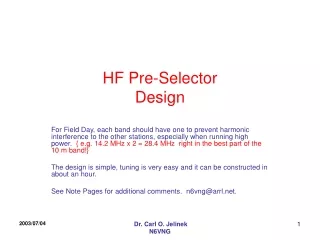
A simple, easy-to-tune pre-selector circuit design to prevent harmonic interference between stations during Field Day operations. Construction, tuning, and usage instructions provided by Dr. Carl O. Jelinek N6VNG. Additional comments and tips included.

E N D
HF Pre-SelectorDesign For Field Day, each band should have one to prevent harmonic interference to the other stations, especially when running high power. { e.g.14.2 MHz x 2 = 28.4 MHz right in the best part of the 10 m band!} The design is simple, tuning is very easy and it can be constructed in about an hour. See Note Pages for additional comments. n6vng@arrl.net. Dr. Carl O. Jelinek N6VNG
Very Simple Circuit Output 2 Turns Input 2 Turns Parts List: 2” O. D. x ½” TOROID Red for HF, Yellow for VHF Power < 300 Watts Use insulated 12 gage wire for the coils. Variable Capacitor ~255 F. 2 ea. Female chassis mount Connectors for Input and output RF tight AL Box [Optional 2P2T switch to bypass] ~14 Turns ~ 255 m F Dr. Carl O. Jelinek N6VNG
Construction Notes • Mount variable capacitor in an RF tight metal enclosure so that the plates have good spacing to the walls. • Mount female bulkhead connectors for the kind of coax your antenna and rig use on the back wall of the box. • Wire each of the 2-turn loops to one of the bulkhead connectors. • A single pole double throw switch may be used to bypass the pre-selector. [optional] Dr. Carl O. Jelinek N6VNG
Tuning Instructions • Terminate one port with a 50-Ohm load that will dissipate full power {It does not matter which port since the circuit is symmetrical.} • Connect an antenna analyzer to the other port and set it for the highest frequency band. {e.g 10 meters } • Tune the capacitor to make sure that the per-selector has a low VSWR and tunes over the full band. If it can’t, choose a smaller value or reduce the number of turns on the larger coil. Test the lowest band that it will tune to. Mark the bands on the box to speed tuning. • Connect your rig, tune to the highest band and test at full power to determine that the toroid does not get too hot. If it does, you need a larger size and perhaps larger wires. Dr. Carl O. Jelinek N6VNG
Comments • VSWR should be better than 1.5:1 over each band. • Each band could use a fixed tuned pre-selector with high quality NPO capacitors. However, I prefer the variable tuned approach so that I can retune to work a lower band at night on Field Day. • You can use a smaller size toroid and wire for QRP rigs. • Use a Yellow toroid for VHF {e.g. 6 and 2 Meters} • Several sections can be ganged together to get sharper tuning, if there is a really bad out of band interference problem, however, tuning may be a little tricky and insertion loss will increase. • Cavities are better at 2 meters and above, but they are large, much more difficult to build and tune. Dr. Carl O. Jelinek N6VNG