Download
1 / 8
80 likes | 102 Vues
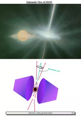
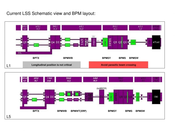
Current LSS Schematic view and BPM layout:. BPTX BPMWB BPMSY BPMS BPMSW. L1. Longitudinal position is not critical. Avoid parasitic beam crossing.

E N D
Current LSS Schematic view and BPM layout: BPTX BPMWB BPMSY BPMS BPMSW L1 Longitudinal position is not critical Avoid parasitic beam crossing BPTX BPMWB BPMWT(XRP) BPMSY BPMS BPMSW L5
Optimum positions are every 12,475nS : 20.569 m; 24.308 m; etc Simulations results give: Range: X +- 375mm: measurement still OK for all beam1/beam2 parameters. Range: X +- 750mm: measurement still OK for nominal parameters, accurate weak beam on strong beam excluded.
Current BPM positions in the triplet:BPMSY BPMS BPMSW Couplers Positions: Optimum Parasitic
Should BPM be warm or cold ? Same Glass metal seal technology for Feedthroughs.Same SIO2 cables used to withstand radiations. • Warm • + Is more accessible for maintenance. • Should be capable of withstanding bake-out to 200°Cwhich is never safe. • Should be checked after each shut-down. • Cold • - Limited choice of materials. • - Is more complicated to design and integrate. • Components should be very reliable. • + Aligned with quadrupole. • + Less prone to modifications once installed.
B1 Button vs stripline B2 Stripline Coupler + Directional Couplers used when the 2 beams are crossing in the same pipe. - 2 beam Outputs means 2 electronic chains with different responses. - Directivity measured as 23 dB at 200MHz is not sufficient to give requested 50um resolution. - Mechanically more difficult to build, less precise. • Electrostatic Pick-Up • - Not able to distinguish beam 1 and beam 2: time windowing should be developed. • + The same electronic chain for the 2 beams, means accurate measurements. • + Easy to build with a good precision, more compact. • + Flat frequency response. The 4 BPMWF installed this shut-down on side of BPMSW will allow to verify this concept.
Current situation Size of a 130mm aperture stripline coupler: Integration issues (1) BPMS was tilted by 45°because too close to M4 line: Consider 300 mm length and 260 mm diameter area to connect the cables. Separate functions by welding the BPM body on a plug-in module.
Current situation Cable integration Integration issues (2) What happen to the cables when the sleeve is installed ? A slot should be used to cross the thermal shield Best place to do cable length compensation: between thermal Shield and cryostat.
Layout and integration studies should take in account area between TAS and Q1. - access and alignment difficult, high radiations, integration of many systems… This area ‘between machine and experiment’ is badly documented: integration issues (3) 1R1: the crowded black hole 1L5: alignment ! …